I have never had much success with analogue electronics. This weekend I wasted 6+ hrs trying to get a pretty simple circuit to work. Then I fried the parts so I can’t work with them any more, this at least is a blessing as it can no longer suck up time and generate additional frustration. I’m going to record the measurements I was able to make here so that I don’t forget what I have already tried (and maybe some kind soul might tell me what I am doing wrong…)
UPDATE: This circuit is now working (see this post), I am leaving the rest of this post unmodified as a record of what not to do.
The circuit I’m trying to make is a voltage converter that will take 19V DC from the input to my Huxley and turn it into 5V DC that can power my Raspberry Pi and all its accessories. That way I can reduce the number of power cables going into my case. I could just use a normal regulator, but that would waste a lot of power as I need 3A available to be sure that the Pi works. 3A x (19-5)V= 42 W burnt up in the regulator circuit.
Instead I decided I would use a switching regulator. I found the ADP2303ARDZ-5.0 on element 14 and it seemed perfectly suited to my application – it can take up to 20V in and give 5V out at 3A. I ordered it along with the recommended inductor and Shottky diode. The package is very small as it is designed to be machine assembled, but I was able to get longer legs soldered on to all of them. I also ordered two units as I knew the chances of me ballsing this step up were very high.
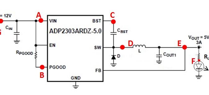
The data sheet is pretty confusing as it is written for both the fixed voltage and the variable voltage versions of the ADP 230X. However I found this helpful link which described the circuit with the fixed voltage version. My parts are slightly different from the version shown in the link but should not be so different as to break it (I think).
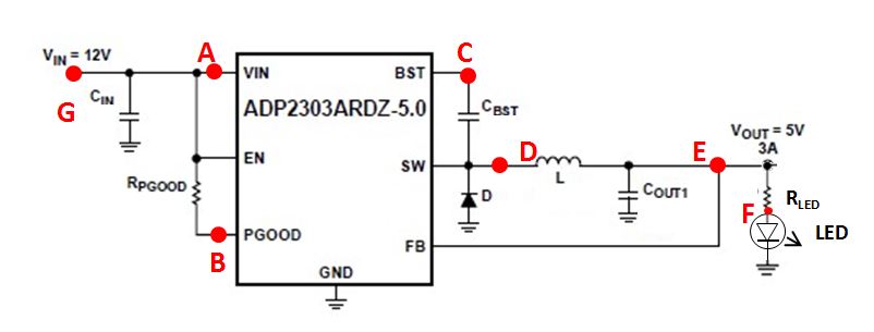
Letters refer to places that I have taken voltage measurements
| Code | Value | Unit |
| Cin | 10 | µF |
| Rpgood | 100 | kΩ |
| Cbst | 0.1 | µF |
| D | SSA33L-E3/5AT Shottky Diode 3A 30V | |
| L | 10 | µH |
| Cout1 | 47 | µF |
| Rled | 330 | Ω |
I tried two configurations – one with the LED removed (i.e. no load) and one with the LED in place. The circuit gives 5.000 V without the LED, but as soon as the LED is in place the output voltage drops away and the Pgood signal at node B goes low. Interestingly it stayed like this even after the LED was removed, but it would return to giving a 5V output after I touched the voltmeter to node D (the SW output).
| Node | Voltage (no load) | Voltage (with load) | Voltage (no load, but directly after LED removal) |
| A | 11.96 | 11.97 | 11.96 |
| B | 11.84 | ~0 (12mV) | ~0 |
| C | 10.02 | 6.6 | 8.49 |
| D | 5.00 | 1.599 | 3.72 |
| E | 5.00 | 1.594 | – |
| F | n/a | 1.589 | – |
All measurements in volts
All this was done on a breadboard with an ATX power supply. I tried a few things to solve the problem:
- Noting that my inductor is 2x the value in the data sheet I put a second identical inductor in parallel to make it 5uH. No difference
- In case I had fried the first chip I tried my backup – no difference
- Since the data sheet mentions the importance of short traces and I am using a breadboard I tried to shorten all the leads, it may have made a difference but I couldn’t tell because while messing with this I foolishly did not turn the ATX off and I accidentally fried the chip
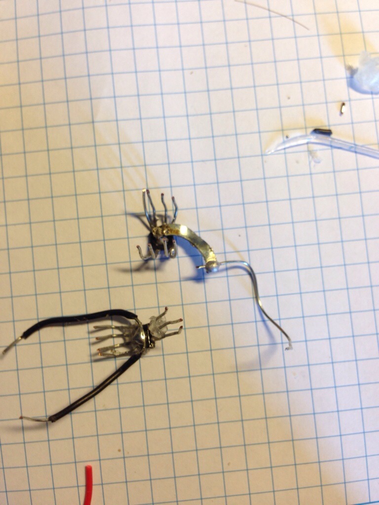
I decided the chip was fried as suddenly the multimeter showed a short circuit between FB and SW, which did not seem right. I tried to change to the other chip and promptly broke one of the legs off in such a way that it cannot be resoldered by mortal hands.
Based on the voltage results it seems like putting a load on it is tripping some kind of safeguard inside the chip (I say this because it the output voltage stays low after the LED is removed). Beyond that I really have no idea what is happening, it is at least heartening I get 5.000V without any load.
I will order new parts and try again…
Hi, have not worked with this device, however a quick review of the data sheet and your configuration would lead me to point you to page 22.
Strip board is bad for coupling noise and there is a specific comment with regard to the feedback pin.
It looks as if the circuit is powered from the USB. It might be that until the circuit is debugged there could be some interaction. Perhaps electrical noise or current limits. How about a couple of new batteries as the power source.
Good luck and perhaps the oscilloscope will help.
Thanks for the tip! It is working now (at least it is with a 12V input, haven’t tried the 19V Huxley supply yet). The problem was the electrolytic capacitors that I was using – you have to use ceramics instead.