After frying two DC/DC converters last time round I had another go at putting together a power supply for the Raspberry Pi controlling my RepRap using an ADP2303 IC. The new circuit still can’t power the Pi, but at least it is now able to hold a 5V output voltage with a small load on it.
My last attempt was able to give a very precise 5V output, but only if there was no load on it at all. My best guess at why it didn’t work was because I built it on a solderless breadboard. The very shaky logic was that either the contacts were causing problems, that the capacitance between the rails of the breadboard was changing the performance or that the length of the traces for some of the paths were too long (the datasheet says that it is important to keep some of the paths short). All of these theories seemed pretty unlikely, but I didn’t have any better ideas.
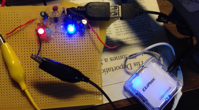
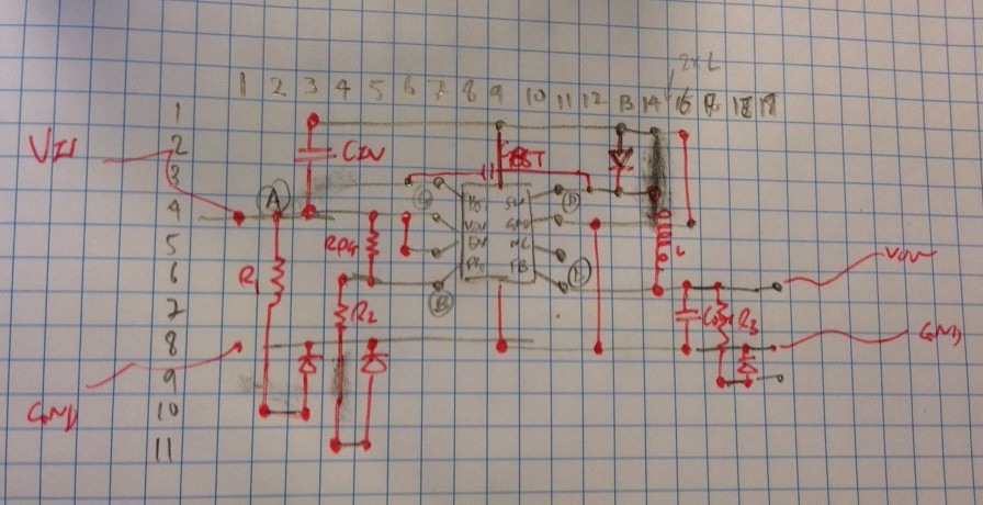
After ordering some new parts I built the new circuit on veroboard. The circuit is the same as the one I built last time but with an inductor value of 5uH instead of 10uH (made by putting two 10uH inductors in parallel) and with two LEDs to show whether there is power at the Vin and PGood nodes. I had very ambitious plans for making the circuit fit on as small a section of veroboard as possible so I drew out a planned layout on grid paper. I quickly realised I’d have to space it out a bit more than the plan, but it was still useful to draw things out first.
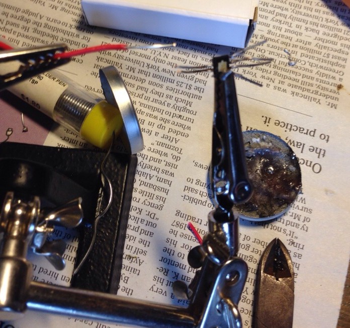
The hardest part of the assembly was putting longer legs on the surface mount ADP2303 circuit. The best way I found was to use some helping hands, apply a little blob of solder to a piece of solid core wire, hold it up against the IC contact and then heat the wire rather than the IC/wire junction. Even with this approach I kept accidentally unsoldering legs I had already attached. I also ended up accidentally joining pin 2 & 3 with a blob of solder (the En and Vin pins), but since they are supposed to be wired together anyway I just left it this way.
I assembled the circuit without the output LED first of all as I wanted to check the voltage output with no load. I tested it with a 12V input and was pleased to get a 5V output. I was surprised that the PGood LED didn’t light up, but think this is just because the PGood output can’t supply any current worth mentioning.
I then wired up the blue output LED and tried it again. Amazingly the LED lit up and I measured 4.96V on the output. I then added a USB socket to the board and plugged in a powered USB hub. the LED on the USB hub also came on. I got a bit carried away at this point and foolishly hot glued a lot of the components in place as I was worried about breaking them while handling.
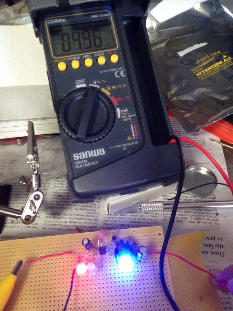
Unfortunately the board failed the test that matters – powering the Raspberry Pi. With the Pi plugged in to the power supply the output LED flashes on and then goes off. Measuring the output voltage shows only 2.1V. I got the same result when I just plugged in the USB hub with a wifi dongle. It looks like it can’t supply the current drawn by these devices. It should be able to as the regulator is rated for 3A and the Pi on its own should not draw more than 1A.
The two questions I’m now thinking through are:
- Why does this work better than the breadboard version?
- Why won’t it work with the higher current draw?
I’m stumped on question 1. You might think that it would be because I’m using a different inductor value this time (5uH rather than 10uH), but I tried this with the bread board too without any luck. It might just be that I made a wrong connection somewhere last time.
For question 2 I’m wondering if it is something to do with the output capacitor. Looking through the datasheet again I saw that it recommends ceramic capacitors for both the input and output capacitors. I couldn’t find ceramic capacitors with high enough values so I have been using electrolytic capacitors. But a capacitor is a capacitor is a capacitor isn’t it? Hmmm…
[Reads data sheet more carefully]
OK looks like I should have tried to understand the complicated terms like ripple current in the datasheet before trying to build the circuit with electrolytic capacitors. According to the sheet the Equivalent Series Resistance (ESR) of the output capacitor is important. This term rekindles some long dormant brain cells from electronic engineering courses – theoretical capacitors do not have any resistance, but real capacitors do. According to wikipedia electrolytic capacitors have an ESR that is around 1000 times higher than a ceramic capacitor. The capacitor I am using for Cout could have an ESR of 30 ohms. The data sheet gives the calculations for working out what the ripple voltage will be for a given Cout. I wonder what ripple voltage my circuit has?
[Does some calculations]
Yikes. According to the calcs the ripple voltage with a 30 ohm ESR would be 26V. This is higher than my input voltage, never mind my output voltage – I think this is what is breaking the circuit when I put more load on it. The switching regulator relies on a feedback loop, and it looks like I am making that loop unstable with the ESR. Interestingly adding a much bigger capacitor doesn’t help. The biggest capacitor I have is 2200uF i.e. about 50x bigger than the one I have currently. However, in the equation for the ripple voltage the ESR term sets a lower bound. Even a 1,000,000 Farad capacitor would still have a 26V ripple voltage if the ESR is 30 ohm!

The ripple current depends on input/output voltages and the inductor used
Looks like I need to go back and order some ceramic capacitors. Based on the wikipedia table of ESRs a ceramic has less than 0.015 ohm ESR, which would give me a ripple voltage of less than 5mV. This sounds more reasonable!
Learning points from this project so far…
- There is more to a capacitor than its capacitance and voltage rating
- I could say that with hindsight I should have gone through the datasheet more carefully and made sure I understood everything before tinkering, but then I think I would still be scratching my head on the functional block diagram. Instead I think the most useful thing would have been to go through the design example – that way I would have spotted the importance of the ESR
- I’ve wasted a lot of time and aggravation fiddling with the circuit, changing components etc. I only worked out what (I think) is wrong when I stopped to write this blog post. I need to remember to decide what I am going to do, do it, test it and then put down the tools and think about the results. Otherwise I’ll just keep tinkering without making any progress.
- Surface mounted components are a real pain to solder, but I could save myself some time by being a bit smarter about which pins to work on. E.g. I dutifully went ahead and soldered an extended leg to pin 6 even though it is “no connection”
- Also surface mounted components have properties that you can’t necessarily find for through hole components – the reason I used electrolytics was that I have never seen a ceramic through hole capacitor bigger than a few tenths of a uF, but it looks like there are loads of surface mounted versions with 10s of uF
- Either I am doing something wrong or the cheap soldering iron I bought for this really sucks. Even though I have been careful about not leaving it on when not needed the tip already looks crusty and horrible. Maybe I need to spend more than 10 bucks and get a proper one
John, 1. “its” not “it’s”.
If the SMDs (Surface Mount Devices) have been giving you so much grief, why didn’t you choose a through hole device? Quick glance at RS gave these options.
SMDs can be a pain to put down, I’d suggest getting a syringe of flux, decent solder and a fine tip for your iron. If you’re really struggling to put these down on a bread-board, there’s a few options of at-home etching kits that you can use to make a single-sided PCB from copper-clad boards. Good luck!
Thanks for the grammar spot.
Sigh – I don’t know why I didn’t find the through hole versions. It would have made things much easier. Since I missed the through hole voltage converter maybe I need to rethink point 6 – perhaps there are ceramic through hole capacitors out there at a reasonable price with the values I needed.
Anyway I managed to fix it last weekend by adding ceramic SMD capacitors. They were easy to mount compared to the buck converter, even though the 10uF one is small enough to be accidentally inhaled. I do need to get a better soldering iron, the one I bought crusts up very very quickly and has a lousy tip. The circuit can power a Pi plus wifi connector with no issues, although voltage does drop to 4.9V. Next step is to mount it and the Pi on the printer somehow.
The interesting thing about the fix was that I assumed that the output capacitor was the problem since that was the one controlling the ripple voltage. However replacing the output cap alone didn’t do it – it only started working once I put a ceramic cap on the input as well. I don’t know why it needs a high quality capacitor on the input as all the magical high frequency jiggery pokery should be happening at the output end?
The switch mode power supplies will leak crap everywhere they can. Best you decouple stuff everywhere, typically we’ll use a 10uF next to a device along with something like a 100nF too. Better safe than sorry with feedback loops.
One question that I’d meant to ask was: are you sure you’ve got enough power budget headroom in the power brick from the printer to support extra 15W max for the Pi?
Hmm… Would be interesting to have an oscilloscope to check what is happening at the input. I am still waiting for my oscilloscope watch from kickstarter!
I haven’t properly checked the power budget. The power supply is a beefy looking laptop supply so probably 60W or 90W? Need to check again. I thought about using the power supply to charge a power bank that runs the pi so that only need to supply average demand but i’m a bit worried about safety of leaving battery charging indefinitely.