One of the most common questions that people ask you when you tell them that you have a 3D printer (shortly after they ask you can you print a gun) is how accurately can you print? My answer to this question has always been stolen from RepRapPro’s specifications page where it describes the accuracy of the RepRap Huxley as 0.1 mm. The various trials and tribulations that my friend Rob has experienced while assembling a 3D printer made from Squirty-printed parts has made me re-examine the answer to this question.
Rob suggested that I test the tolerance of the 3D printer by printing what he described as a Minecraft (TM) doughnut. This is a bit like a doughnut, only square. After printing one I could measure the inner and outer dimensions and compare it to the dimensions in the design to understand what the tolerance of the printer is. The idea of having an inner and outer dimension to measure is that you can tell if the plastic squidges slightly outside the boundary of the part – if this was the case the outside of the doughnut would be too big while the hole would be too small. This post describes my adventures with the aforementioned Minecraft doughnuts.
Of course rather than simply make the doughnuts like a sensible and productive person I instead started thinking of various ways I could improve (i.e. unnecessarily complicate) the method to measure other performance parameters on Squirty. The complication step is an important part of the creative process for me and usually results in a project that should have taken a couple of hours stretching out to many weekends without any conclusive result. However each new idea I had to complicate the Minecraft doughnut concept was too exciting not to be included in the initial print.
Complication number one. One of my early prints was done in two parts – a stand and a trophy that fitted inside the stand. To print this I had to set a clearance for the trophy to fit in the stand’s slot. Due to the ribbed nature of 3D printed objects they are apt to get stuck when inserted in a slot that is too tight (this is possibly the most inadvertently obscene sentence I have ever written). It is therefore important to make sure that the slot has enough clearance added to it to accommodate the object without sticking. As well as printing a Minecraft donut I could also print a series of solid doughnut “holes” with different tolerances to see which hole fitted best without getting stuck – this would give me the ideal clearance for any slotted object.
Complication number two. I have always been very interested in the print in place mechanisms that I have seen on Thingiverse like Emmet’s gear bearing. These designs include multiple moving parts that are printed in one go with the gears and bearings to connect them already in place. One critical factor for these types of print is how close you can print the objects before they fuse together. Again, the Minecraft doughnut method could allow me to test how close together I could print objects before they fuse. If the hole for the doughnuts was printed already inside the outer portion of the doughnut I could test whether it could be removed without sticking.
Complication number three. Of course rather than just bash this out on AutoCAD I wanted to do all of this on OpenSCAD and to make it customisable so that it could easily be changed to use different tolerance settings. Using openSCAD would also allow me to upload a customisable version to Thingiverse later.
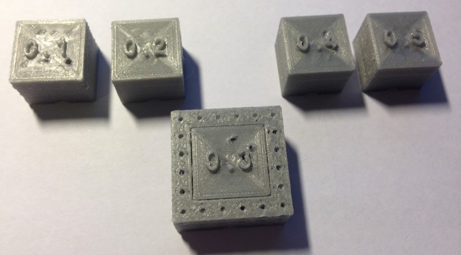
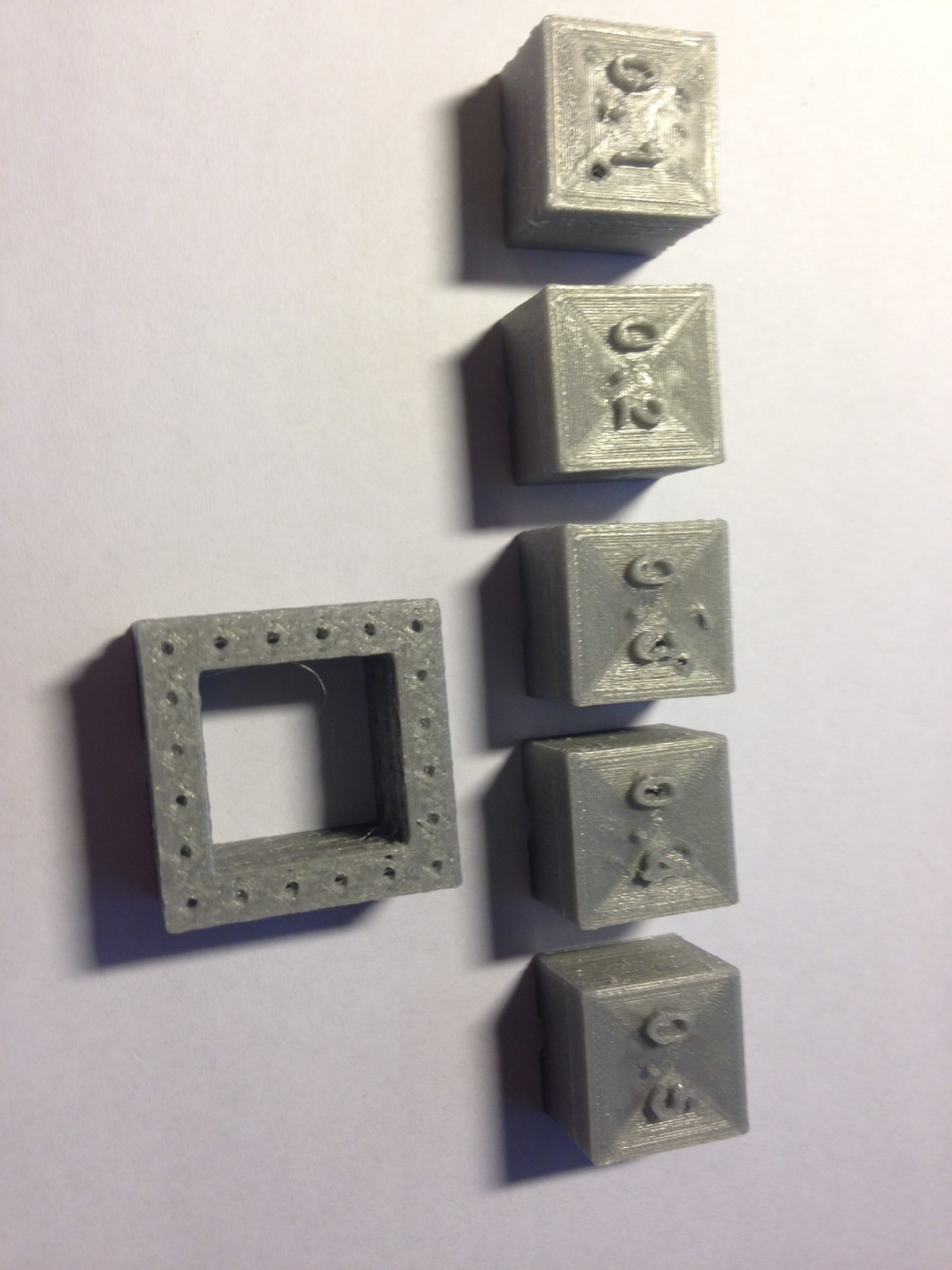
Complication number four. At this point I started to realise that it would be quite difficult to keep track of all the different doughnuts and doughnut holes that I was generating especially when they would only differ from each other by a few tenths of a millimetre. Fortunately I had recently discovered the fantastic write library for OpenSCAD This would allow me to label each doughnut or doughnut hole that I was printing so I could remember what size it was supposed to be.
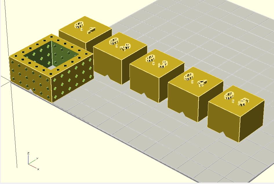
Complication number five. As I started trying to make the monstrous array of Minecraft doughnuts that had been created as a result of complications one through four I realised it was going to take forever to print. All the doughnuts and holes had lots of volume and so they took a long time to finish. I started wondering whether there was a way to cut down on the volume for these simple shapes. I decided to try and reduce the print volume by making the inner Minecraft donut holes hollow. I did this by creating a hollow shaft inside the inner donut holes. I didn’t want to the shaft to go all the way through the donut hole so I had to find a way to cover it. Since the printer can handle a 45° overhang quite comfortably I covered the shaft by rotating a cube by 45° and subtracting it from the hole shape (this builds on the removal key I made for the Grassy Knoll).
The outer portion of the doughnut was too thin to be made hollow in the same way that I had hollowed out the inner portion. Instead I made a series of horizontal and vertical shafts made by rotating a 45° cuboid. This left the doughnut looking something like a Swiss cheese.
Having followed relentless logic to arrive at a Minecraft Swiss Cheese Doughnut made of polylactic acid as the solution to all my problems, I proceeded to print. The first attempt did not work so well, mainly because my printer bed was not fully level. Also in the OpenSCAD code I had made a mistake when inserting the clearances. It should have been arranged so that the donut hole cube had a clearance of the assigned value all the way round the cube. However I accidentally only subtracted the value from the width of the cube once which meant that the clearance was halved and all the cubes were way too tight a fit. I was however able to use the results of the print to check the X and Y dimensions of the doughnut “holes” and they were all within 0.15 mm of what they should have been.

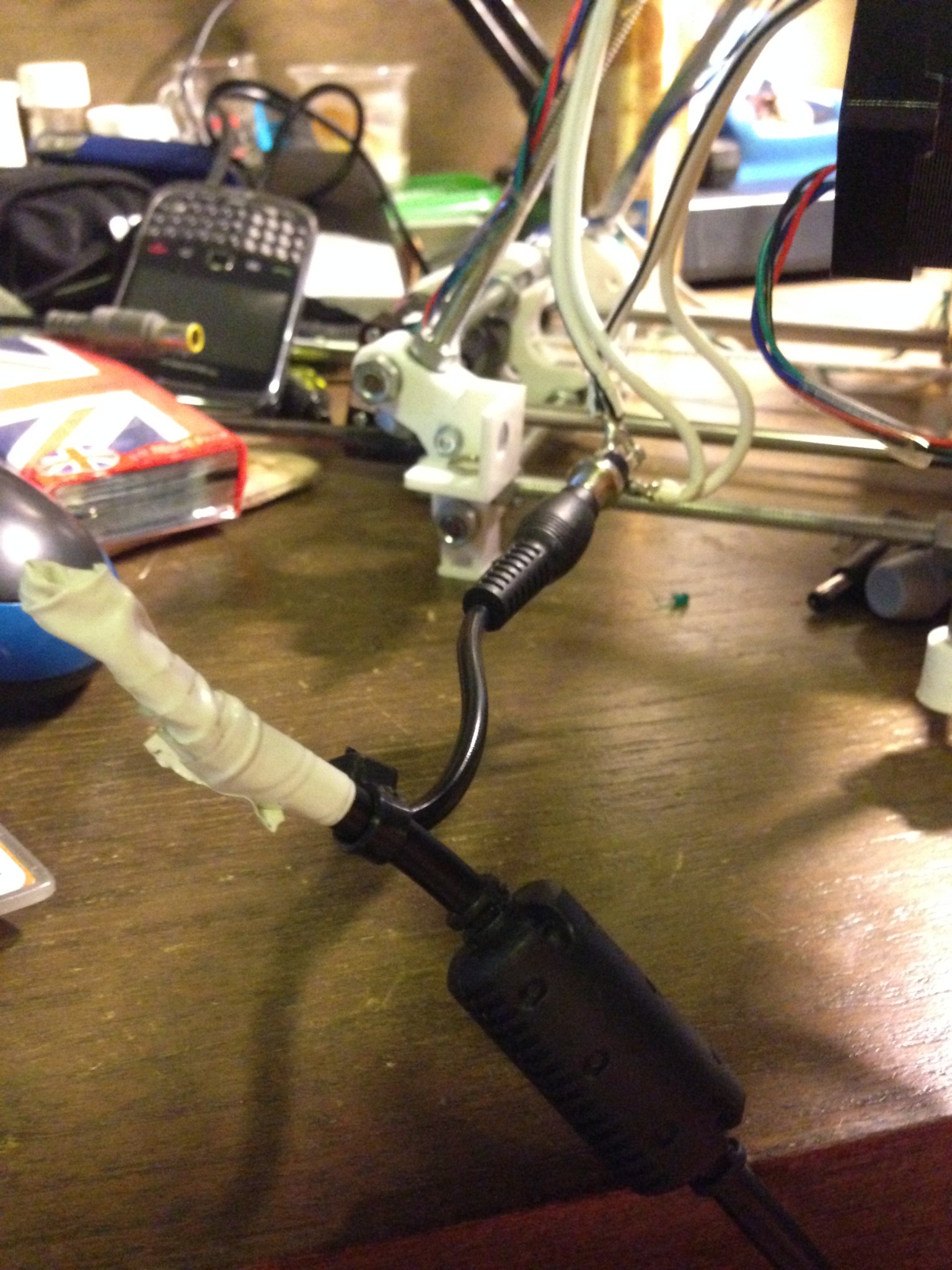
My second attempt took place a weekend later and resulted in complication number six. The print started out well and I went out for a while to let it finish. However when I returned home I found that the printer had stopped working about 5% of the way into the print. I have been having some problems for some time where the printer seems to lose power and I have to fiddle with the power cord to get it working again. Playing with a multimeter for a little while showed that the power cord for my printer’s 19V power supply had a defective plug. Fortunately I was able to dig out a old 12V power supply that had the same plug. I chopped the working plug off the 12V power supply and attached it to my printer’s 19V power supply and everything started working nicely again.
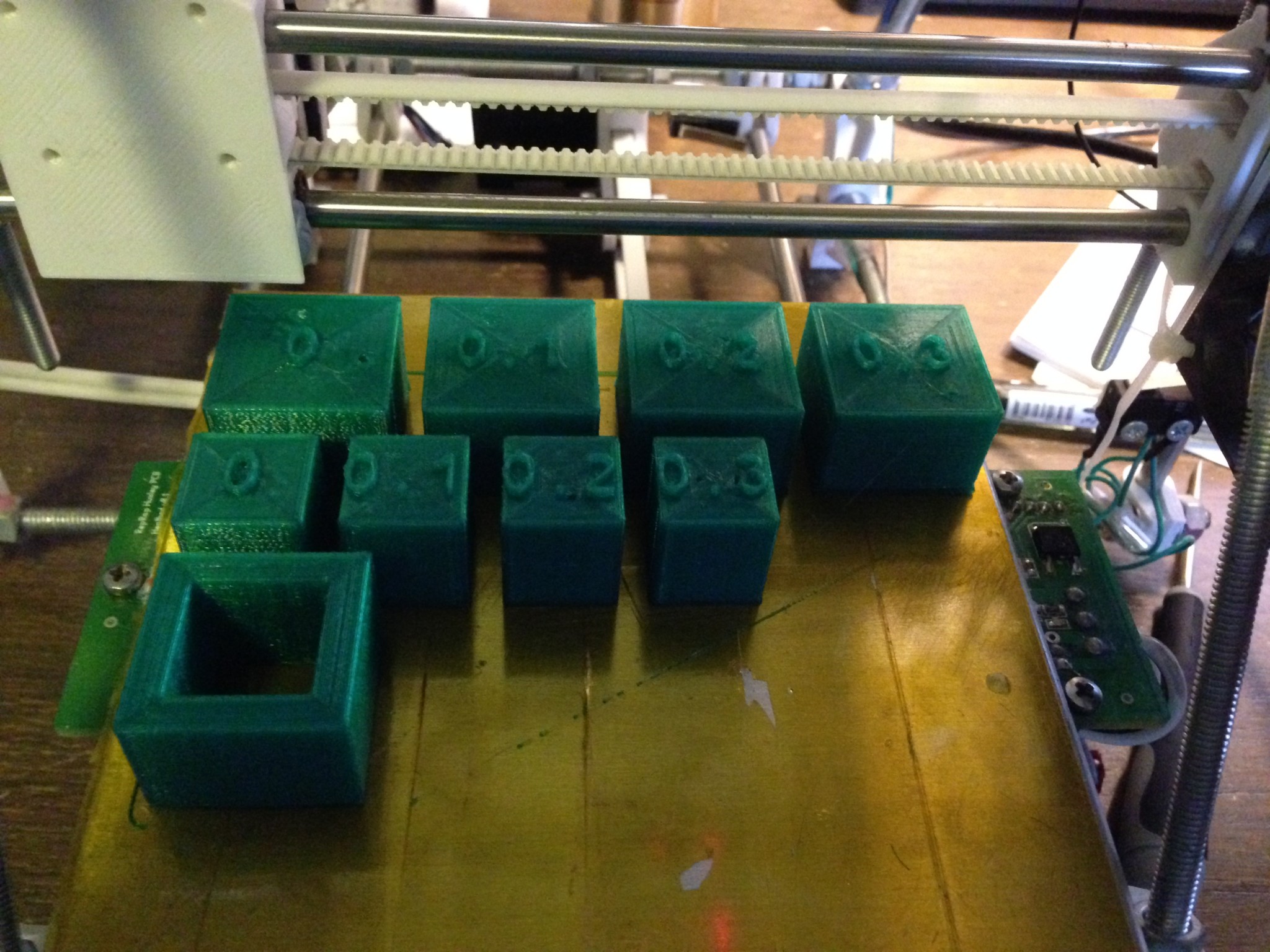
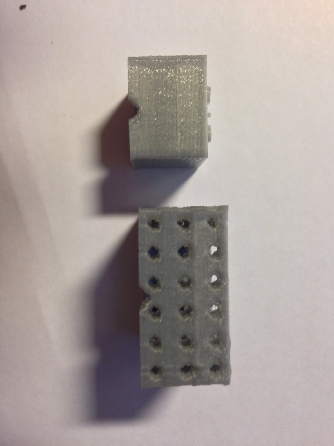
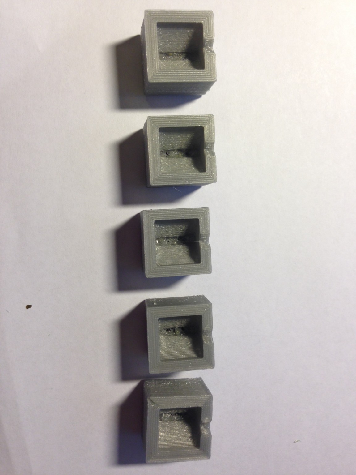
The abortive print that was left on the plate by the power failure did give me some idea about the answer to my question about the tolerance required for print in place parts. The doughnuts that were printed with less than 0.3 mm clearance were not even recognised as separate parts by slic3r – the outer and inner parts were just fused together. For some reason in one of the parts with 0.2 mm clearance it seemed to confuse slic3r so badly that it interfered with the shafts that were printed in the outer part of the donut and they did not all print. I was able to remove the hole from the doughnuts printed with 0.3 mm and 0.4 mm clearance however I’m not sure if this would work if the doughnut was printed to a reasonable height rather than just a few layers.
By this point it was already quite late in the weekend so I was not able to print a whole new plate of doughnuts. However I did have enough time to print just one doughnut outer and a range of doughnut inners with different clearances that might fit within the outer. This time it worked and I was able to try and slot the doughnut holes in into the doughnut outers. The 0.1mm hole wouldn’t fit at all. The 0.2mm hole fitted snugly into the doughnut with a bit of effort but I couldn’t push it all the way through – it got stuck at the slight lip on the bottom of the print. The 0.3mm slid without any effort, but it was still tight enough to stay in place if you pick up the doughnut and give it bit of a shake. 0.4mm and 0.5mm can slide through no problem.
In conclusion the printer is accurate to +/-0.15mm and 0.3mm seems like a good clearance when printing parts that are intended to fit together (I guess this makes sense – you’d expect the clearance required to be around twice the max error on the dimensions?)

That seemed to be somewhat straightforward, perhaps you could have added more features to your donuts? (apologies for spelling, I’ve just gotten back from ‘merica)
One thing that I’ve noticed when printing objects is that the number of perimeters/ solid infill layers made up by slic3r isn’t necessarily what I would have predicted. To that end, I suspect that adding the swiss-cheese effect might have actually increased your print time/ material usage due to all the extra edges that you’ve added. Any thoughts?
I’m not sure that you’ve answered your original exam question here… the only part that you have showed to be directly measured (rather than relative via mating faces) is oversized by 0.15mm, but if this is a constant over sizing (e.g. print a 15mm donut and get 15.15mm outer-diameter) then you’ve got a systematic error right there, my friend and a problem with your perimeter widths 😉 How do the inner holes look? Are they all oversized/ undersized? I’d print a few different sized donuts to give a range of representative measurements. Is the CAD released now?
Of course all this might be because you’ve been rockin’ a beta-release of slic3r. There is a (very recent) stable version of slic3r (v1.0.0 stable), which might give different results.
Finally, a comment about tolerances, based on my experiences of machined parts in the aerospace industry. We tend to use 3 or 5 axes machines that will give a nominal tolerance to metal parts of +/-0.1mm. If a slot is specified as 20.0mm and a mating part is then 19.6mm nominally (e.g. 2 ends, double the tolerance: 2*2*0.1=0.4mm) the parts at the extremes of what will be accepted against a drawing, will have what’s called a transition fit, this will be (potentially) high friction and not usually work. If we’d want something to slide past something else, an extra gap is left. So for the above example the mating part would have a (nominal) dimension of 19.4mm to allow a guaranteed 0.1mm clearance on both sides of the mated surfaces. Tolerance build-up is a pain.
Thanks for the comments Rob! I guess that means subscriptions are working?
You might be right on slowing down the print because it has to do more perimeters. I might do a timed run, or maybe I could weigh one swiss cheese versus one normal as a proxy. I’ve done something similar but more ambitious on a recent print that I’ll share soon.
Interesting stuff on the tolerance build up. I’m surprised the nominal tolerance is only .1mm for a milling machine.
I don’t know where your suspicion on my tolerances come from, but I shall print some varying size doughnuts and measure to check.
I will put CAD up soon, need to comment it a bit.