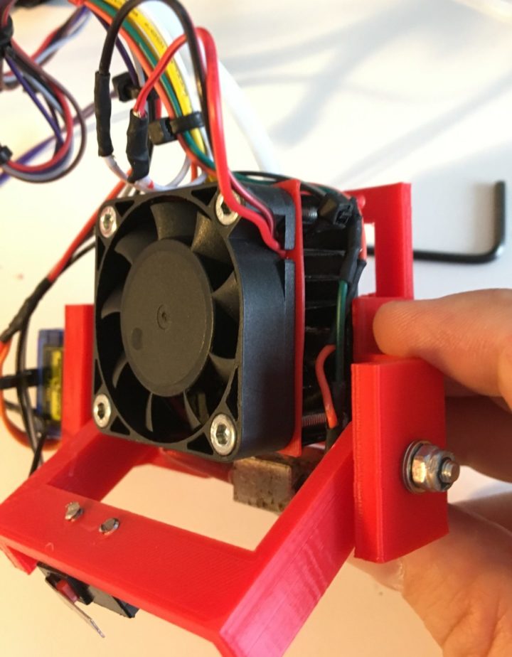
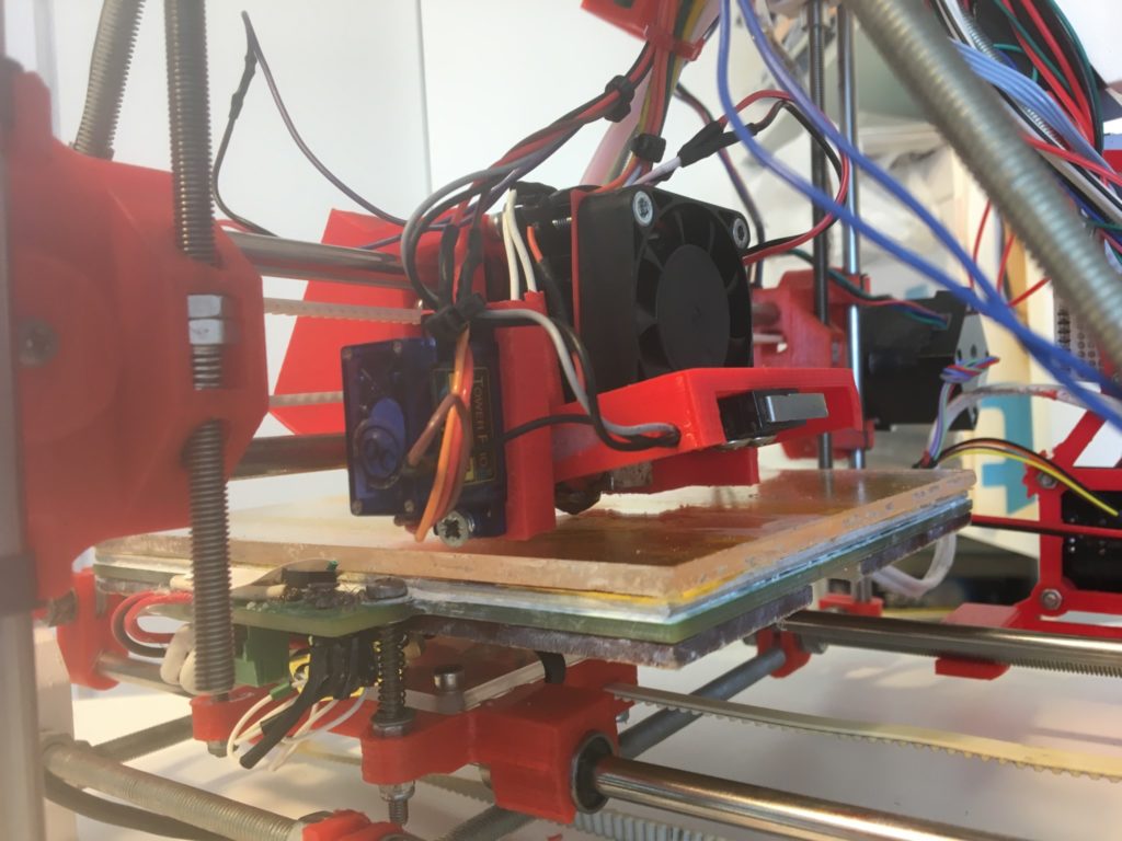
In previous posts I described a z-probe modification I made to Squirty the RepRap. The major issue with this z-probe was that the point probed was about 30mm away from the nozzle, which meant that the probe could not reach the entire bed. I’ve designed a new version that resolves that issue. By mounting the microswitch on the same side as the hotend the microswitch for the z-probe is almost directly underneath the nozzle. Mounting the z-probe in this way required creating “wings” that stop the servo arm from colliding with the z-axis at low/high x values. In this post I’ll describe how to assemble and set up this z-probe on a RepRap Huxley. I hope this is useful for anyone out there who is still, like me, printing on a 5+ year old design. If you do try it then please let me know how it works out!
The video below shows the probe in action.
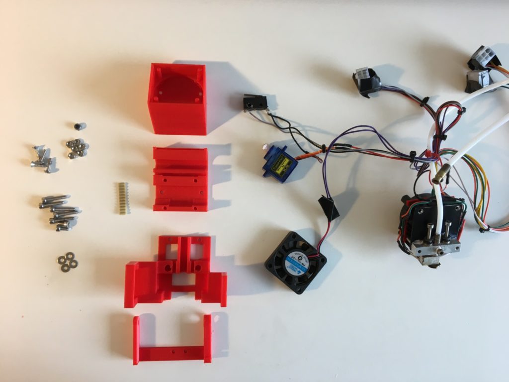
Begin by printing four parts (stls on Thingiverse)
- Fan shroud
- X carriage base
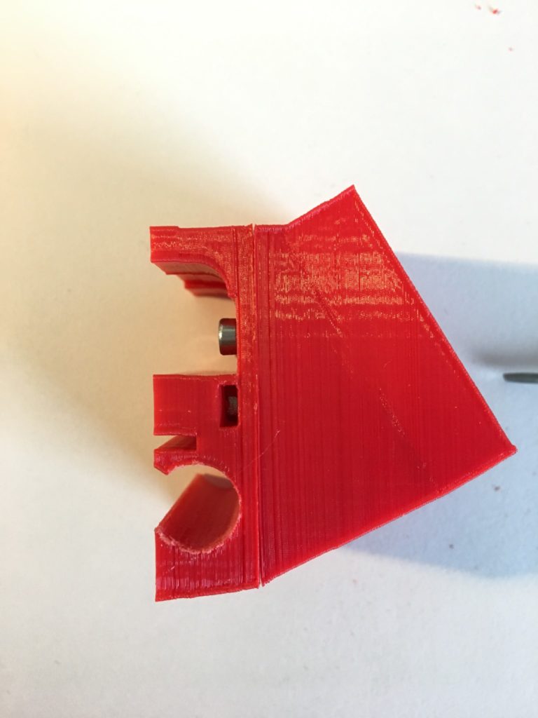
- Nozzle mounting (I suggest slicing this at a 45° angle for increased strength)
- Servo arm
If you wanted to modify the designs then you can clone them from Onshape
You will also need the following non-printed parts:
- Tower mini servo motor, with mounting holes drilled out to 3mm
- Microswitch with mounting holes drilled out to 3mm, and tabs cut/filed short
- 27mm piece of pulley belt
- 5x M3 x16mm bolts
- 2x M3 x6mm bolts
- 6x M3 nuts
- 1x M3 locking nut
- 4x M3 washers
- 4x M3 x10mm screws
- If you don’t already have a ducted fan, you’ll need a 24V 40mm fan
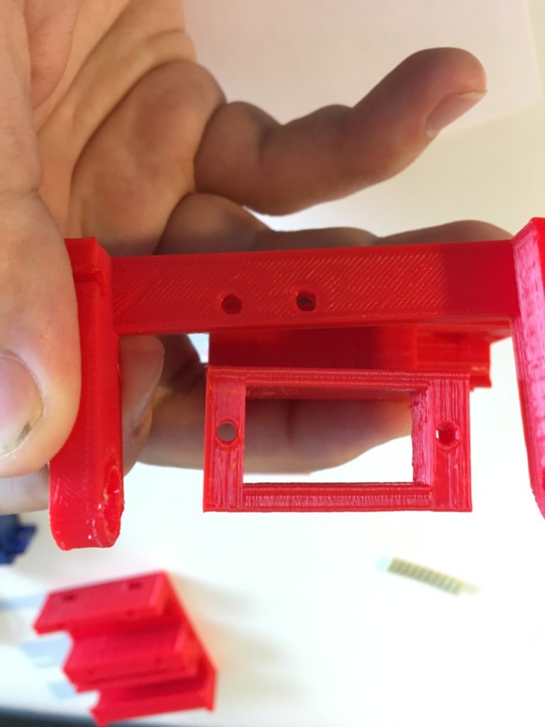
I printed the nozzle mounting part at a 45° angle to make the “wings” as strong as possible and to stop the layers from splitting when adding screws. All the other parts were printed with normal settings.
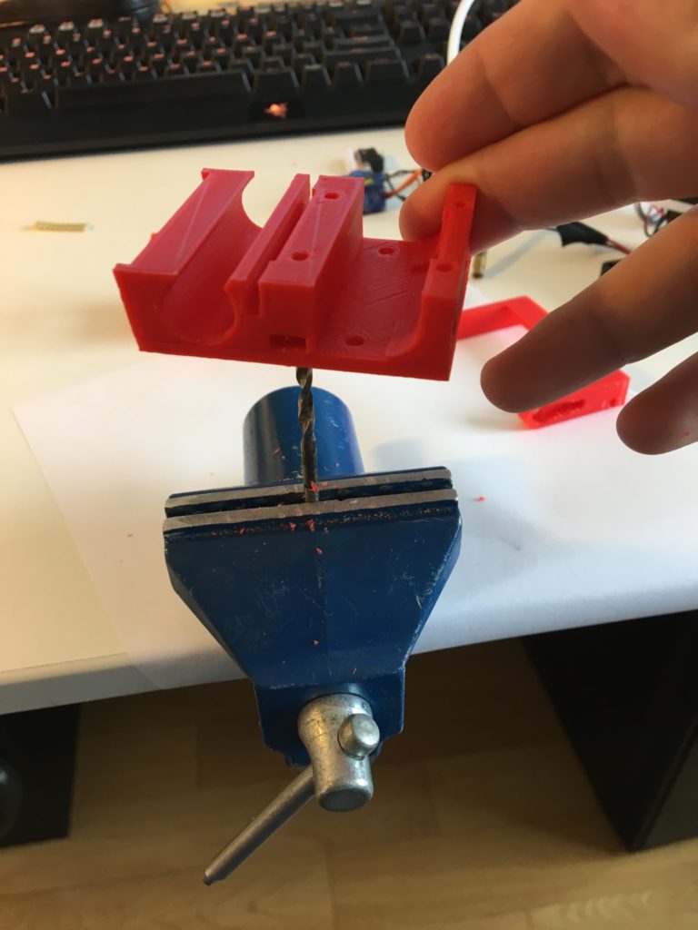
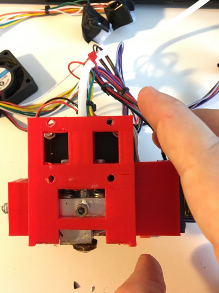
Remove any support material and fettle all holes with a 3mm drill bit except the holes for the servo and microswitch (these take M3 screws so should be tight). Use a rounded file to make the x carriage accept a linear bearing (should be a tight fit).
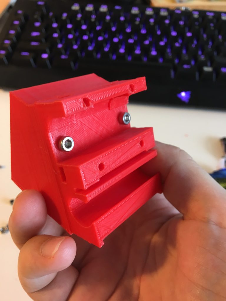
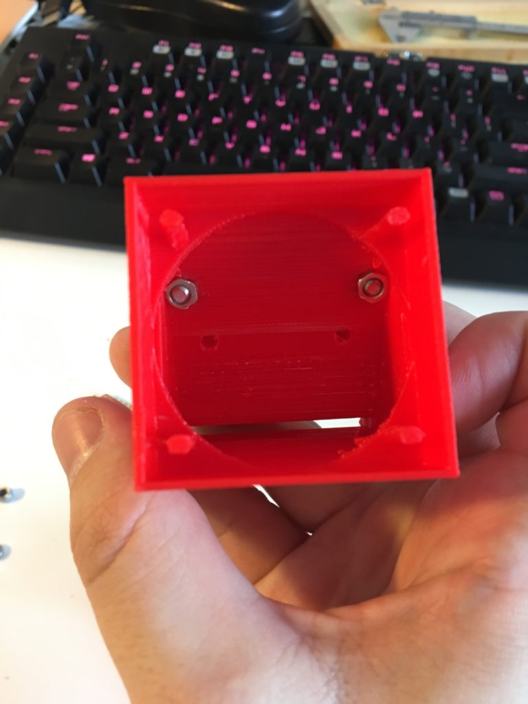
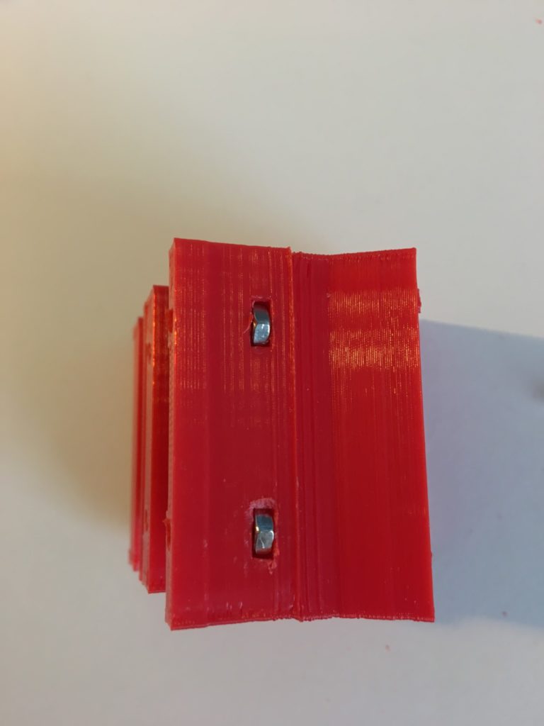
Attach the fan mounting to the x-carriage using the two short M3 bolts (6mm) and two M3 nuts. Be careful throughout the assembly process to avoid damaging the pillars that are inside the fan shroud – they are delicate. Drop 4x M3 nuts into the nut pockets in the x-carriage. There are two at the top, one on each side. “Drop” might be a little ambitious – you may have to tap them in using a screwdriver and a small hammer.
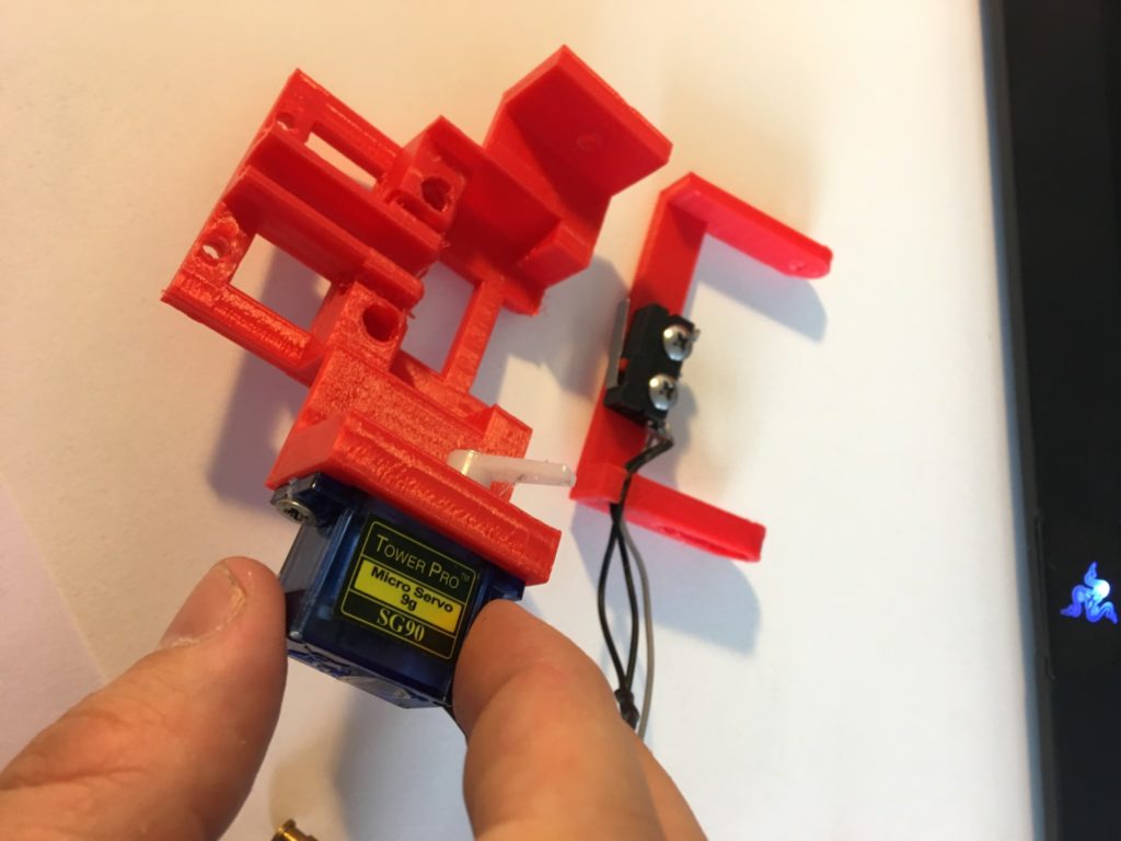
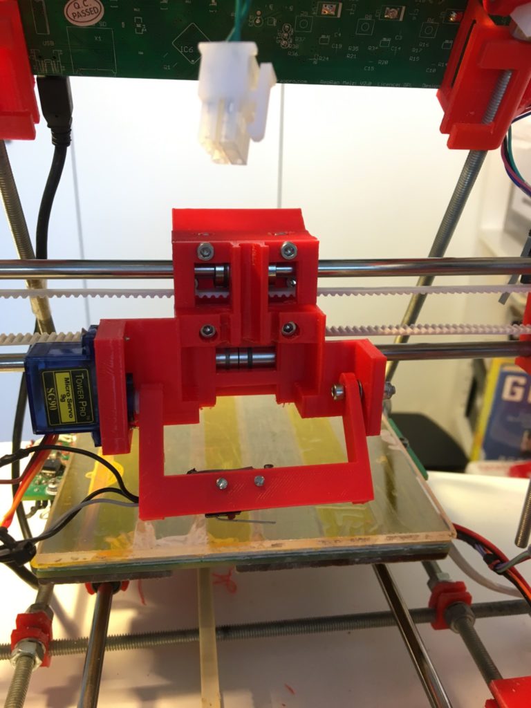
Screw the servo into the nozzle-mounting. Add the servo horn to the servo if you haven’t already. It is important when attaching the servo horn to make sure that the servo’s range of motion includes both the “stow” and “deploy” probe positions. Usually the servo will have 180° of motion. Only 90° are needed, so you can allow some play on either side and then adjust the stow/deploy angles in software. Screw the microswitch into the servo arm. The wires going to the microswitch should clip neatly into the little pocket on one side of the servo arm to avoid them dragging on the print bed.
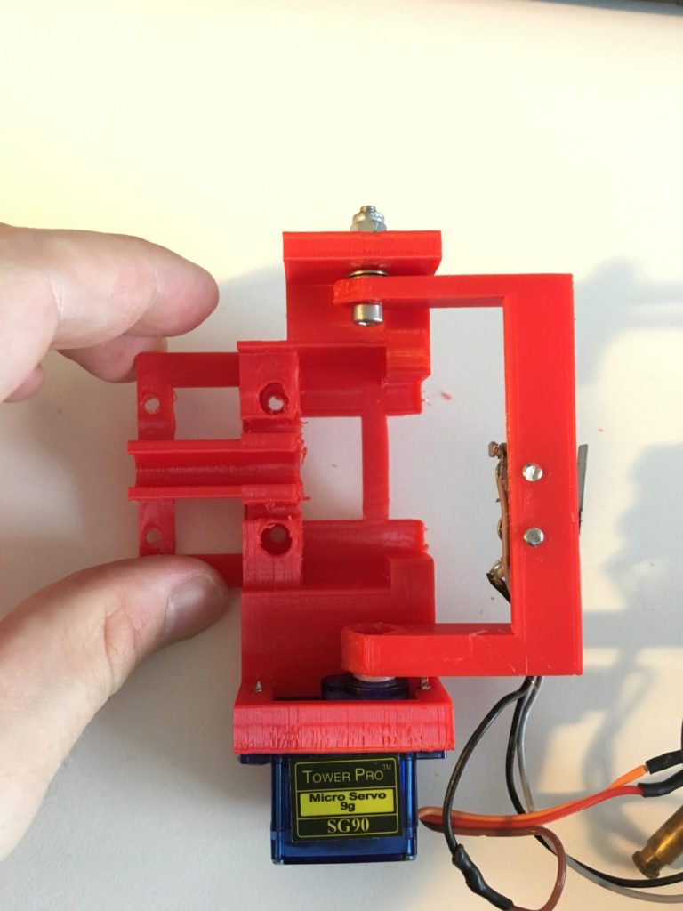
Attach the servo arm to the nozzle mounting. On the servo side the printed part should slip over the servo horn (you might need to cut the tip off the horn). On the other side use a M3 16mm bolt with four washers (two each side of the attachment to the nozzle mounting piece) and the M3 locking nut.
Check that the hotend assembly fits neatly into the nozzle mounting. Check how much the nozzle juts out – it should be just clear of the nozzle mounting. Too much clearance and the fan will blow on the heating block rather than the nozzle, too little clearance and you risk the nozzle mounting catching on the printbed. Add/remove washers to the bolts in the cooling block to adjust the clearance. Remove the hotend assembly.
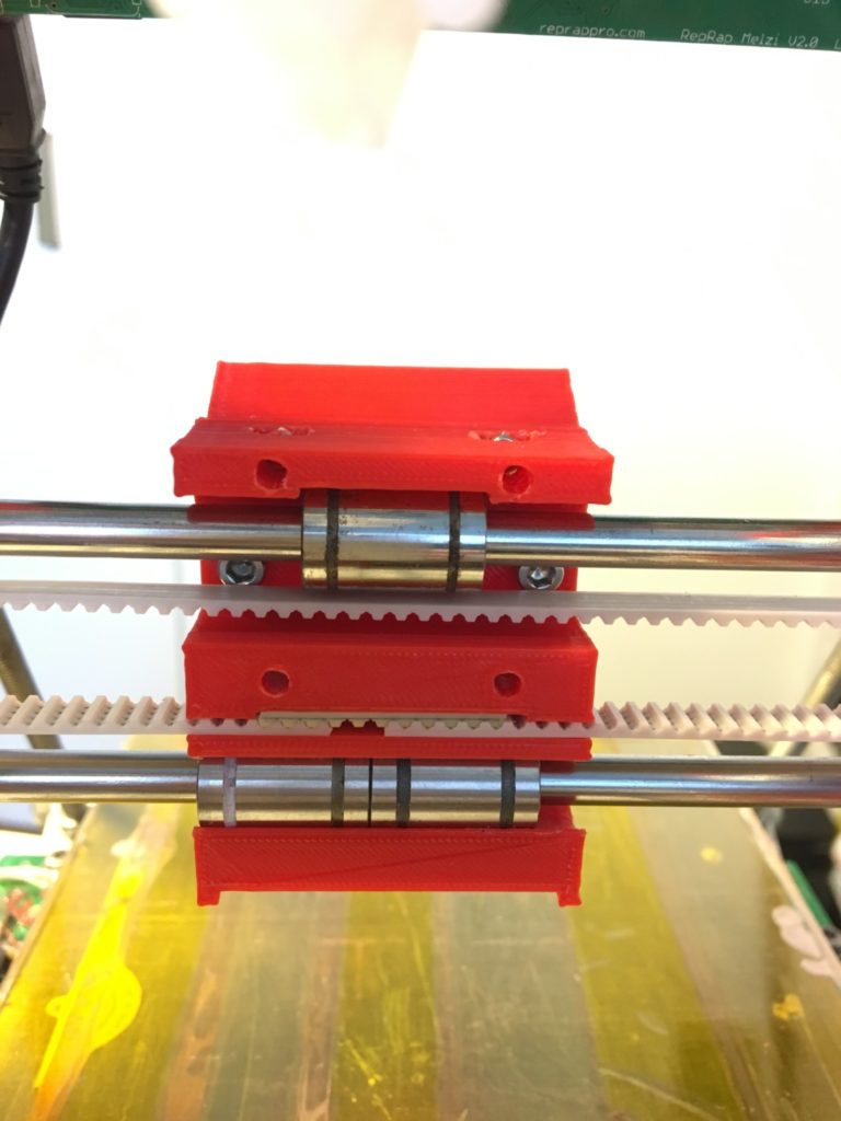
Attach the x-carriage to the printer by sliding the linear bearings into the lower track of the x-carriage, then tilting it to capture the upper linear bearing. To avoid later gnashing-of-teeth double check that you have installed it facing the right way, i.e the fan shroud side should face towards the front of the printer. Join the pulley belt in the x-carriage under some tension using a small piece of belt.
Use 4x M3x16mmm bolts to attach the nozzle mounting to the x-carriage.
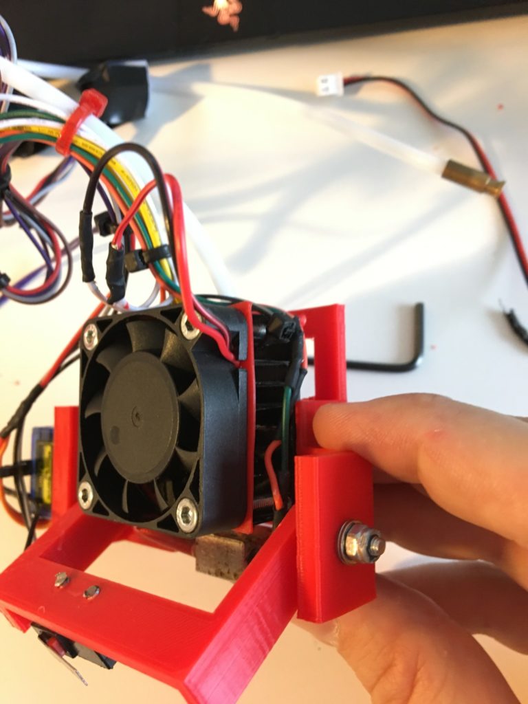
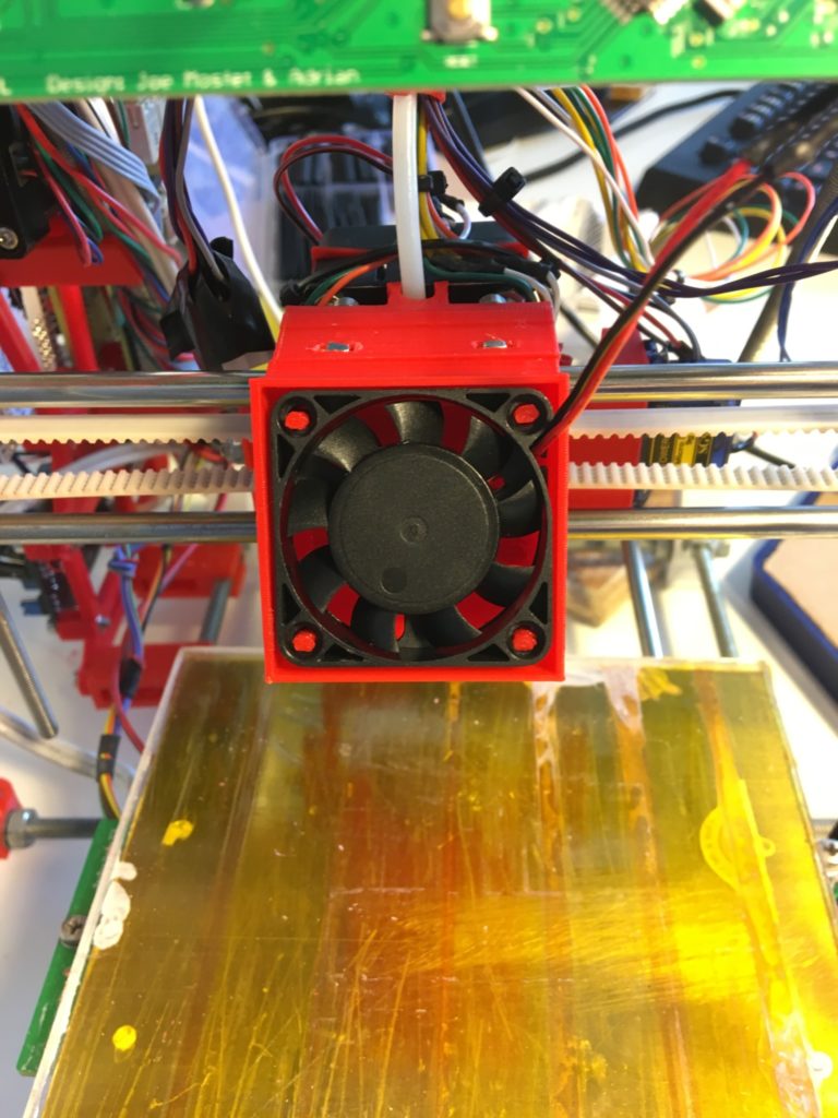
Attach the hotend assembly. Drop the ducted fan into the fan shroud. Reattach any wiring, reattach the bowden tube from the hotend assembly.
Double check the wiring, then it’s time to try it out!
Start by setting the probe angles. Use the M280 command (set servo angle) to find a good “stow” and “deploy” angle. E.g. M280 P0 S70 sets the servo to 70°. For me, around 70° is a good stow angle, 175° is a good deploy angle (I like to have the servo arm above horizontal when stowed to allow some room for servo jitter). Be careful that in either position the servo is not blocked – if the servo is continuously trying to force the arm through the x-carriage then the motor will wear out quickly.
Add these angles to your Marlin configuration file. E.g. my SERVO_ENDSTOP_ANGLES line reads…
#define SERVO_ENDSTOP_ANGLES {{0,0}, {0,0}, {175,70}}
While you are editing your Marlin config file you should also set up the z probe offsets. You can measure these yourself or trust my values below (z probe landing is 2mm ion front of nozzle and 7mm to the left). It would be very easy to redesign the servo arm to make both these values 0, I might do this some day.
#define X_PROBE_OFFSET_FROM_EXTRUDER -7

#define Y_PROBE_OFFSET_FROM_EXTRUDER -2
Ignore the Z_PROBE_OFFSET_FROM_EXTRUDER value, this should be set using the terminal (M851 command) and stored in EEPROM.
The penalty for the small x & y offsets are that the servo arm needs some considerable height to deploy. To avoid crashing the servo arm into the bed, set the following values (note all these lines should already be present in your Marlin configuration, just search for the string and edit the value).
#define Z_RAISE_BEFORE_HOMING 30

#define Z_RAISE_BEFORE_PROBING 30

#define Z_RAISE_BETWEEN_PROBING 5

#define Z_RAISE_AFTER_PROBING 5
Note that 30mm is quite a large rise in height, and this will happen as soon as you tell the printer to home Z. MAKE SURE THAT YOU HAVE ENOUGH VERTICAL SPACE FOR THE 30MM RISE BEFORE YOU HOME Z. It is very easy to forget that the nozzle is already quite high (because you just finished a tall print) and then absent-mindedly tell the printer to home Z, causing the carriage to rise 30mm and crash into something. Before starting a print confirm that the carriage is not too far from the print bed and, if it is not, then manually bring it to a reasonable height.
Be aware that the ducted fan shroud will collide with the Huxley’s frame at about z=55mm for low and high x values, i.e. much lower than the Huxley’s nominal build height. This was an issue with the “official” ducted fan attachment as well. It may be possible to increase the collision height, however it shouldn’t be much of an issue unless you want to print something which is both very wide AND very tall. If your slicer includes gcode at the end of a print that moves the nozzle to the bottom left of the print bed it is wise to remove it, as otherwise any print higher than 55mm will cause the fan to crash into the frame (not the end of the world, but if you have been printing for any length of time the sound of blocked stepper motors probably strikes terror into your heart).
With the configuration file set and uploaded to your Melzi you can test Z probe deploy/stow using M401/M402, or you can go straight ahead and run a z-probe repeatability test using
M48 P10 V4 E
This will do 10 probes of the print bed in the same location, stowing the probe between measurements, and report the standard deviation of the results. I am always astonished by how good this is given all the potential sources of lash etc. in the servo arm. My standard deviation is 0.004598mm.
Send: M48 P10 V4 E

Recv: M48 Z-Probe Repeatability test

Recv: Positioning the probe...

Recv: 1 of 10   z: -22.292848 mean: -22.292848   sigma: 0.000000

Recv: 2 of 10   z: -22.299766 mean: -22.296306   sigma: 0.003459

Recv: 3 of 10   z: -22.296802 mean: -22.296472   sigma: 0.002834

Recv: 4 of 10   z: -22.298284 mean: -22.296926   sigma: 0.002577

Recv: 5 of 10   z: -22.304956 mean: -22.298532   sigma: 0.003954

Recv: 6 of 10   z: -22.307428 mean: -22.300016   sigma: 0.004901

Recv: 7 of 10   z: -22.300262 mean: -22.300050   sigma: 0.004538

Recv: 8 of 10   z: -22.296060 mean: -22.299552   sigma: 0.004445

Recv: 9 of 10   z: -22.291858 mean: -22.298698   sigma: 0.004838

Recv: 10 of 10   z: -22.297790 mean: -22.298606   sigma: 0.004598

Recv: Mean: -22.298606

Recv: Standard Deviation: 0.004598
All you need to do before printing is set your Z probe offset using M851. Do a Z home, then use the paper method to work out how the offset needs to be adjusted. E.g in terminal output below I needed to adjust the z probe offset by 0.9mm to -18.8mm. You should an offset around this number.
G28 Z

[...]
[…]
Send: M114
Recv: X:70.00 Y:70.00 Z:0.90 E:0.00 Count X: 70.00 Y:70.00 Z:0.90
Recv: ok
[…]
Send: M851
Recv: echo:Z Offset : -19.70
Recv: ok
[…]
Send: M851 Z-18.8
Recv: echo:Z Offset ok
Recv: ok
[…]
Send: M500
Recv: echo:Settings Stored (380 bytes)
Recv: ok
You should now have a working z-probe!
Designing this thing has been a very long process The videos below show earlier versions of the z-probe concept, which you can read more about in previous posts.