Following on from the previous post I redesigned the z-probe holder to position the microswitch closer to the nozzle. I also forked the latest version of the Marlin firmware to correct some problems I was having with the leveling behaviour. The video below shows that the autoleveling seems to be working, but I need to do some checks to understand how successfully it is correcting for any tilt in the bed. I also need to make further design changes to the z-probe itself. This post includes more details on how I designed and set up V2.
Designing V2
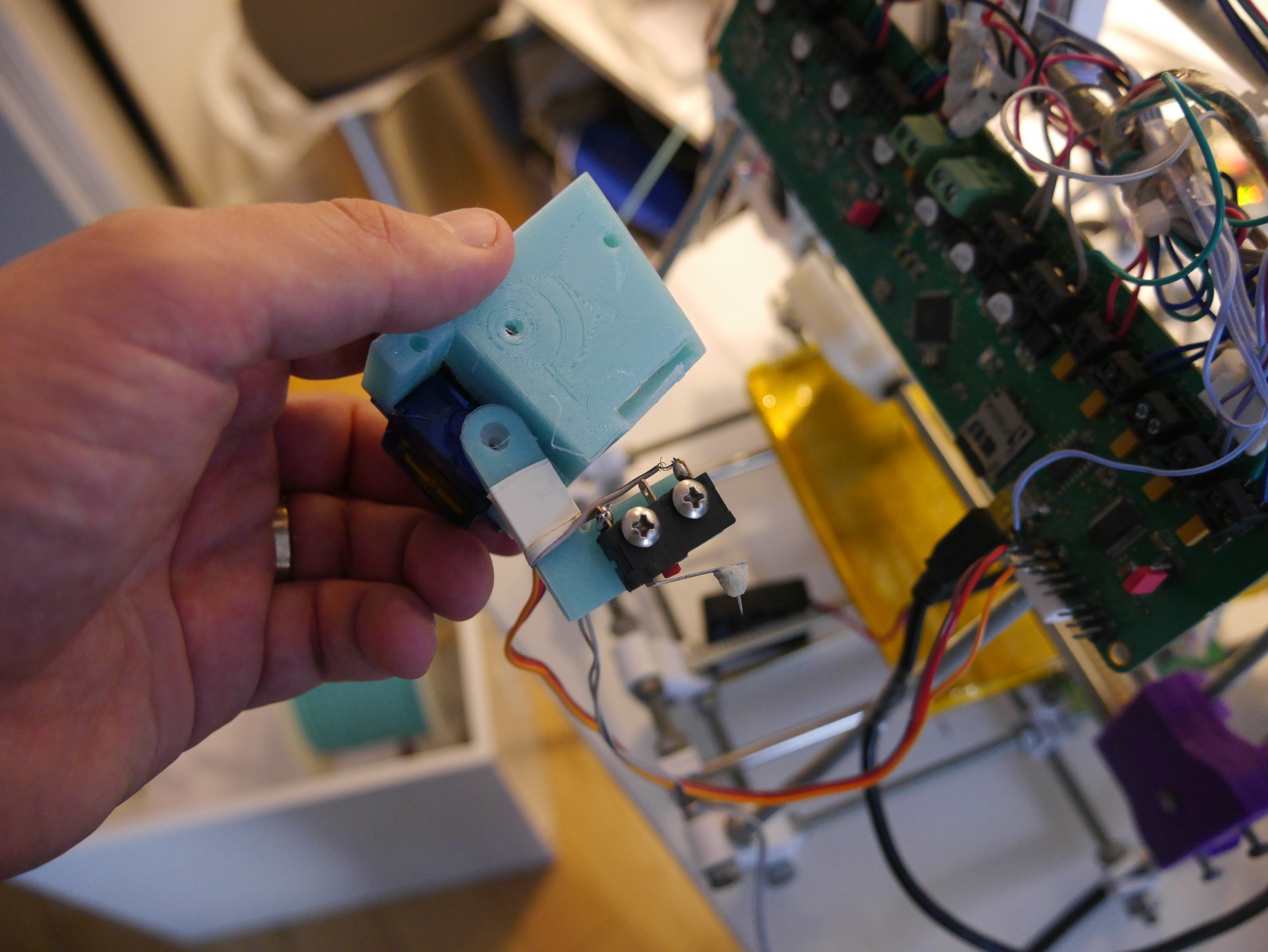
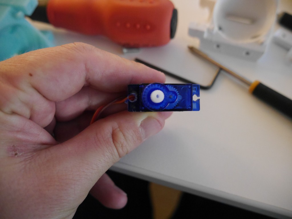
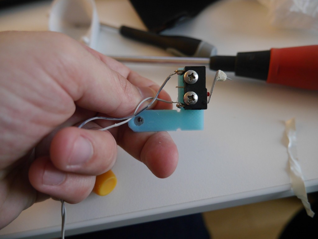
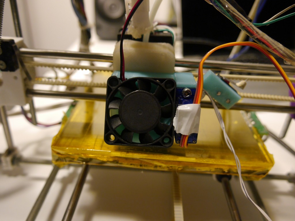
In my last post I described the V1 z-probe and the main problem I had with it – the probe was too far away from the nozzle so I could only measure a small portion of the bed. The new version was intended to correct the problem by bringing the deployed probe as close as possible to the nozzle. I flipped the servo around so that it is facing towards the nozzle and made a longer bracket to hold the microswitch that reaches under the x-carriage.
I encountered some problems with OpenSCAD while doing the redesign. In the previous iteration I decided to combine the z-probe servo mount with the ducted fan mount. I imported the original stl into OpenSCAD and then added in a pair of lugs that could hold the servo. It was difficult to produce a shape in OpenSCAD that would attach securely to the fan mount but which also would not jut into the inside of the duct. OpenSCAD doesn’t have a way of understanding the geometry of an imported STL, which makes creating a new shape that meshes smoothly with an imported one difficult. OpenSCAD also behaved somewhat unpredictably with the ducted fan STL and frequently failed to render.
The original ducted fan mount was designed in Solidworks, and I read recently that OnShape is a beta web-based CAD program developed by ex-Solidworks employees. I gave it a go and was very impressed – it is sketch based, very fast and very easy to pick up. I was able to import the original Solidworks file and quickly make a new version of the fan mount. I’m not quite sure how the sharing works on the OnShape site but you should be able to find the part once logged in by searching for “Modified Huxley Fan Mount”.
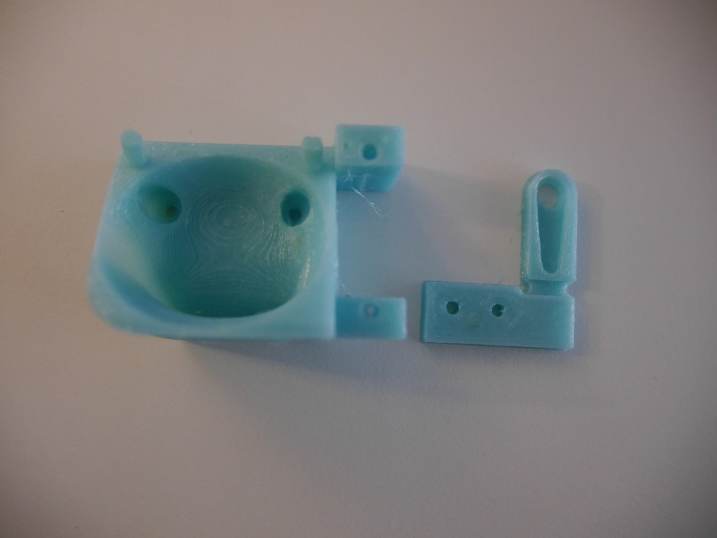
Because of the way I am mounting the servo in V2 I had to make a 90 degree overhang that required support. I have never had much luck with support before, but decided to give it another go. No matter how I tweaked the parameters in Slic3r the support layers just didn’t stick to each other. Eventually, I inspected the gcode and saw that layers were being “missed out” – there were layers with no support at all. I did a bit of googling and found that slic3r defaults to a 0.3mm layer height, which is not possible to print with my 0.3mm nozzle. I ended up supporting the overhang with a solid cuboid of plastic that I hacksawed off afterwards.
It is irritating that Slic3r won’t let me do support, but I do really like the latest version’s OctoPi integration. You can automatically upload gcode files to an OctoPi server. It would be nice if it would then start printing them automatically too, but it is still pretty nifty.
I designed the microswitch bracket for the V1 switch in OpenSCAD, so it was very easy to change the parameters to work for V2.
Why V3 is needed
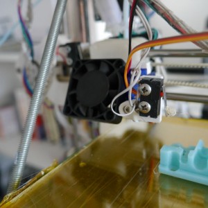
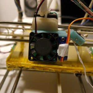
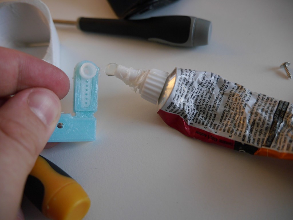
The V2 fit together pretty neatly. You can see the assembly sequence below.
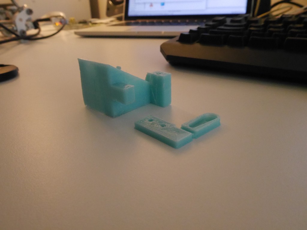
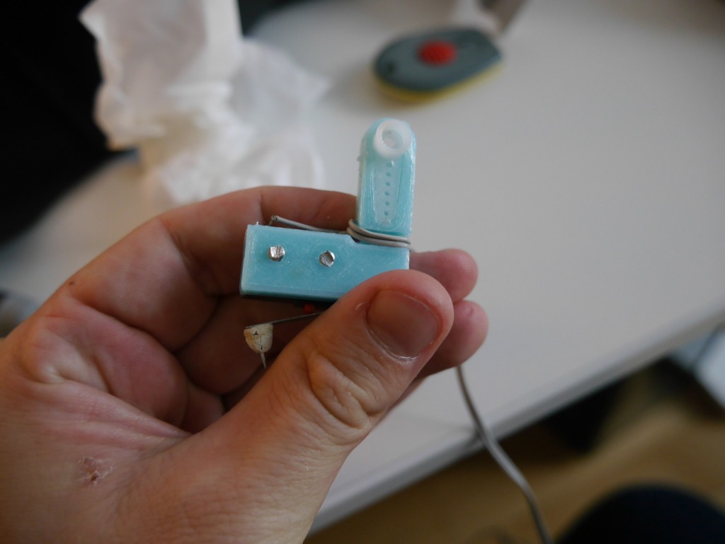
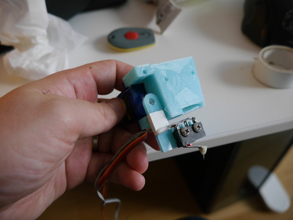
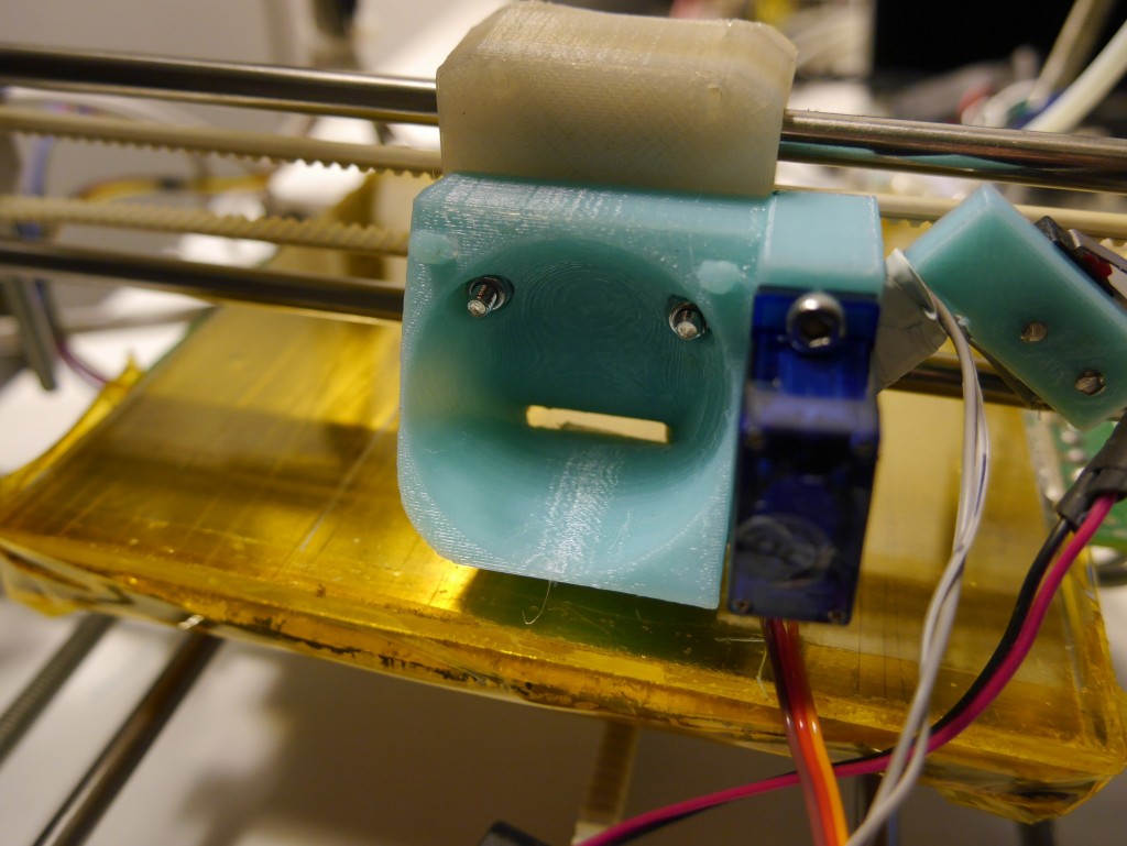

I designed this version to try and keep the microswitch as close as possible to the nozzle. Unfortunately, I made it so close that the switch bumps into the x-idler when the carriage is at the right hand side. I had to move it back a few mm by using some M3 nuts as spacers. Even with this modification it is a big improvement over the previous version. In V1 the probe was offset from the nozzle by 31mm in the x direction and 66mm in the y direction. In V2 the probe is only 3mm away in the x direction and 31mm in y.
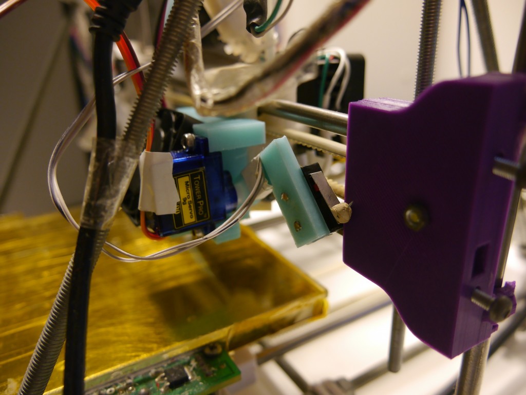
The servo can also hit the frame on very tall prints. For these two reasons I’d like to do another iteration of the probe assembly.
Firmware malarky
After getting all the hardware in place I tried a z-home. The printer moved the nozzle to the center of the bed, deployed the probe, lowered the nozzle until the microswitch clicked and then brashly retracted the probe. This smashed the probe into the bed – it needed to raise the nozzle before retracting the probe. I found that the developers of Marlin already knew about and had fixed this issue in the latest release candidate version of the firmware. I was able to fork this version and adapt it to work with Huxley. It is on github here.
Next steps
Although I can see the z motors working while a layer is printing, the first layer of the print does not seem to be as even as I like. On one side of the print bed the beads of plastic are merged together and quite squashed, but on the other they are slightly separated and more rounded. The most important next step is to do some tests to understand how tilted the bed is and to what extent the auto leveling is correcting for the tilt – s far as I know it could be “correcting” in the opposite direction.
I also would like to do another iteration of the z probe mounts to avoid some of the problems I described in this post.