Last month I posted about installing a ducted fan on Squirty. After installing the fan I read issue 42 of MAKE magazine and became excited about two ideas to try for testing out the ducted fan. As is often the case, I got a bit distracted trying out these ideas so it’s taken me a while to get round to answering the original question of whether the ducted fan helps with print quality or not (short answer is yes, but more work needed for Squirty to match commercial desktop printers).
The issue of MAKE includes the 2015 3D printing buyer’s guide. This year they used a very nice quantitative approach to rank print quality across different printers. They created a set of test print items, each one designed to test a specific aspect of print quality such as bridging performance or dimensional accuracy. They also created a guide for evaluating each aspect on a scale 1-5. The nice thing about this is because they ranked all the major desktop printers against this guide I can use these prints to see how Squirty compares to printers made by PrintrBot or MakerBot.
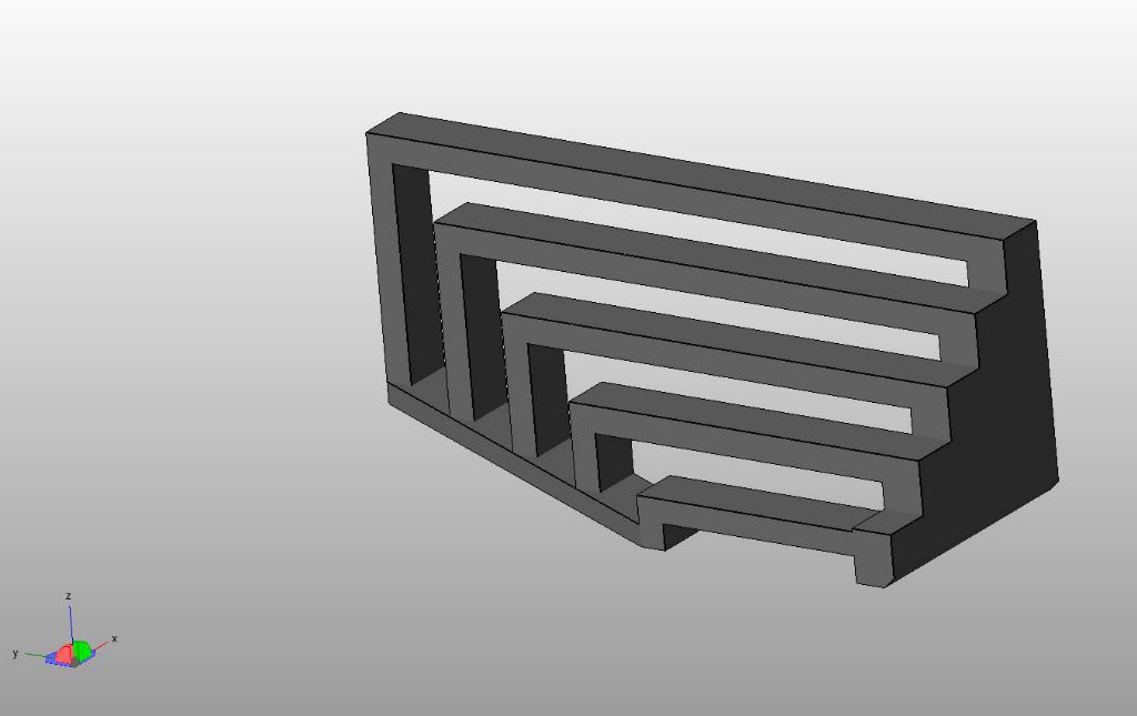
The main idea of putting in the ducted fan was to improve bridging performance so I used MAKE’s bridging test piece. This is made up of a series of bridges of increasing span. The idea is to see which bridge the printer fails on. The shortest bridge is 20mm and the longest is 60mm.
I tried the bridge piece with three fan settings. The first was with no fan. The second had the fan on at 57% Pulse Width Modulation. When I installed the fan I worked out that 57% is the right setting to give 12V, which is what the fan is rated for. I did the 3rd run at 100% PWM which is 19.5V (I know the maths don’t quite work here – the values are based on trials). 19.5V is much more than the fan is rated for, so I don’t really want to run it like this for extended periods. I’ve got vague, half-formed fears of the fan sticking somehow, overheating and catching on fire. You can see the results in the photos below.
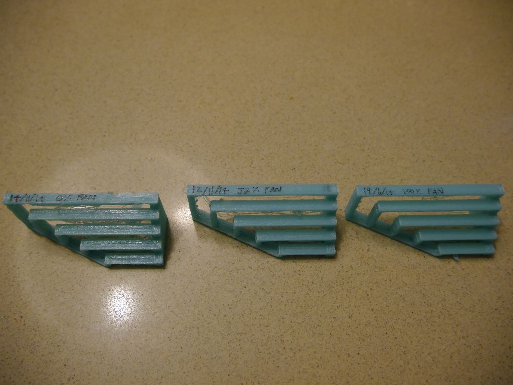
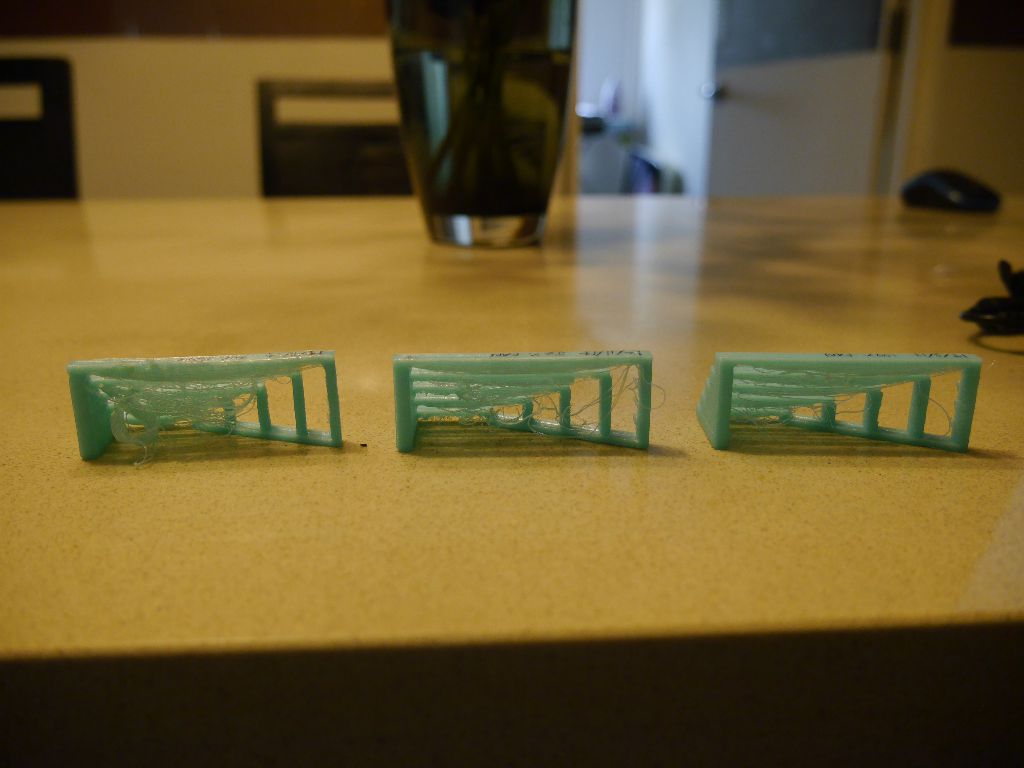
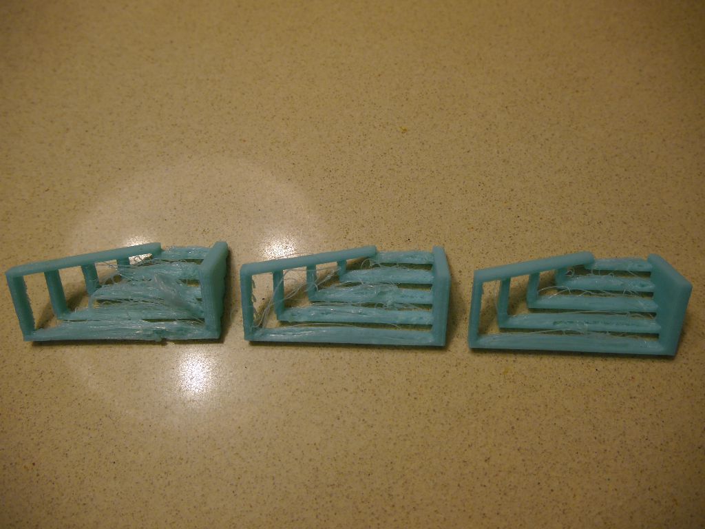
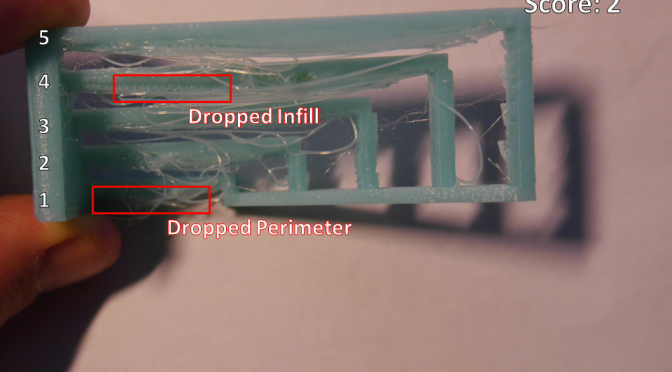
My photography skills are not great, but I think you can still see in the images that there is an improvement as the fan speed increases. I’ve evaluated them using the MAKE guide which says:
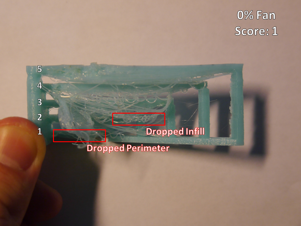
- Assign a “1” if any bridge has dropped infill.
- Assign a “2” if only the longest two bridges have dropped infill.
- Assign a “3” if none of the bridges have dropped infill, but all have dropped perimeters.
- Assign a “4” if the shortest two bridges compiled without any dropped perimeters.
- Assign a “5” if all bridges compiled without any dropped perimeters (drooping of less that 2mm is acceptable).
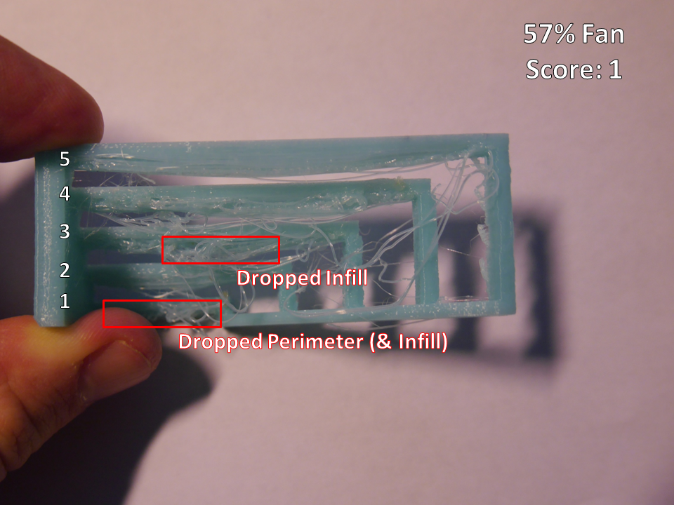
The wording is a bit off since you should evaluate “1” if any bridge has dropped infill, but evaluate “2” if only the longest two bridges have dropped infill. I think the only sensible way to interpret is that “1” should really read “if any bridge other than the longest two has dropped infill”. Based on this interpretation I think the 100% fan gets a “2” rating and the others get “1” ratings. The 57% fan is much better than 0% fan, but for some reason it dropped infill on the bottom layer (maybe because of the heated bed?).
I’ve annotated some pictures below showing what I’ve classified as dropped infill etc.
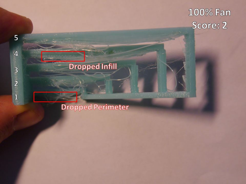
My conclusion is that ducted fan does help a lot, but it’s not the only piece of the puzzle. I think I will have to play with my slicing settings to get better prints. In particular I think the bridging speed is probably too low.
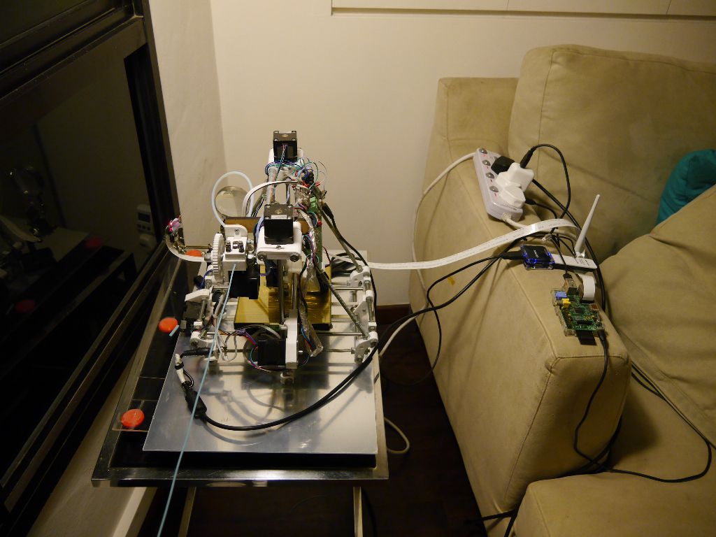
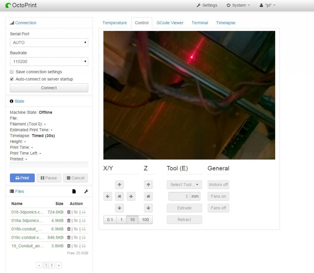
So that settles ducted fan for now. However, I mentioned that I got two ideas from MAKE about how to test the bridging. The first was to use the MAKE test piece, the second idea was to use OctoPrint. OctoPrint is a piece of 3D printing host software. Previously I have always used Pronterface which was the default for the RepRap when I bought my kit. To allow my printer to run in a different room from my computer I set it up to run on a Raspberry Pi and then controlled it using a VNC connection (see Stealth Printer I). This worked OK, but the VNC could sometimes be a bit slow and unreliable. The exciting thing about OctoPrint is that it comes with a web interface which makes everything faster and easier. It also has built in support for a webcam to allow you to view what the printer is doing over a network and create timelapses of prints. To complete all the coolness a kind soul created a Raspberry Pi SD card image called OctoPi that has everything you need to run OctoPrint on a Pi using the Raspberry Pi camera module.
The timelapse is what interested me from a bridging perspective because I thought it would allow me to see what’s happening when a print fails. In the end it wasn’t so helpful for working out what’s happening during bridging but it is fantastic for making setting up prints smoother and less frustrating.
Installing OctoPrint was very straightforward. I set it up with the camera on a long cable mounted on a set of helping hands (with the assistance of blu tack).
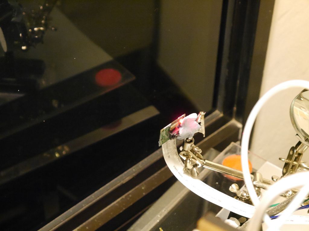
The performance was a bit iffy at first – it kept losing the connection to the printer half way through the print. I think this was something to do with my router and wifi adapter rather than the software though. I replaced the wifi connection with an ethernet powerline connection and it now is very reliable. It is very straightforward to use. Currently I have the camera mounted at the top of the printer which gives a reasonable view of what’s going on. I think it is a bit too close though – focus looks a bit fuzzy.
I’m still figuring out the timelapse. The timed mode has two settings: “Interval” and “Timelapse Post Roll (in seconds)”. The first setting is how often it takes a photo to make the timelapse video, but the second setting had me scratching my head. Initially I thought it was how long it would hold the final image on the screen “Post Roll” but it turns out that instead this is the total length of the video that it creates. E.g. if you have a 1 hr print with “Interval” = 60s and “Timelapse Post Roll” = 30s it will create a 30 second long video with 60 frames, i.e. framerate of 2 fps. The video below was created before I worked this out, which is why it is so short.
As you can see it is not so useful for working out what is happening during bridging. Even if you create a much longer video you can’t bring the camera close enough to the print head to a decent view of how it’s printing (it goes out of focus).
One more cool thing about OctoPrint – since it’s used over the network you can set up port forwarding on your router and then check on your prints when you are out of the house. You can even cancel a print that isn’t going well. I’ve tried this out and it works fine. Of course putting the printer on the web comes with the risk that someone hacks into it and sets your nozzle temp to 1000 deg C to burn your house down. The developers of OctoPrint recognise this and include a password feature that you are strongly encouraged to set up.
You can see in this post how easily I get distracted and sucked in to other projects. There is just so much cool stuff that can be done and so little time! Also I tend to get stuck solving problems that are tangential to the goal I start out with. I’ve got one more random aside that provides a good example of this – while trying to work out how fans affect bridging performance I ended up trying to work out how my ISP sets my IP address…
How did this happen? Well, setting up port forwarding for OctoPi drove me nuts initially because I couldn’t get DynDNS to work. You need dynamic DNS for accessing your home network from the internet because unless you pay for a static IP the address of your router on the internet will change at the whim of your internet service provider. DynDNS provides an address that your router can automatically link up to so that you effectively have a static IP. I first set up DynDNS about a year ago for accessing a NAS and it worked fine. However when I tried to set it up for OctoPrint I couldn’t connect. I also found the NAS connection wasn’t working any more. Long story short I changed ISP a little while ago to MyRepublic and they use some fancy virtual IP setup. The clue was that my router thought that my external IP was an address that was different from the address I saw when I asked google what my IP address was. This setup stops DynDNS from working, but MyRepublic solved the problem for me by selling me a static IP for a one-off fee of $50. Pretty reasonable!
OK that’s enough rambling for this time. Back to working on the web interface for BeerBot…
You do have a strange fascination with using Blu-Tack for fixings, don’t you? Is the repeated failures you force upon yourself some form of self-punishment that we should be concerned about?
Interesting to see an objective rating for printer competence. Would be nice to see how little Squirty compares to the big boys. In fact, it’d be bloody useful to see a minimum rating for models on Thingiverse, e.g. “you’ll need a bridging rating of 3 for this print”.
OctoPi sounds like the answer. I may have asked Santa for a Raspberry Pi this year, so that’s just saved me lots of grief. Couple of additions I’ve planned for my installation though, interested to hear your opinion:
1. Relay controlled from the GPIO on the RPi to allow remote master power control. Theory being that the RPi can switch it on and off to prevent the fans running perpetually. Can also be used for emergency power control.
2. Case temperature sensor. Not sure how I’d plumb this into the RPi, but in operation it’d trigger warning emails if the temperature goes above a certain level, or possibly a software based shutdown if the case temperature continues to rise. If I’m cunning I’d be able to rig it to operate a simple hardware shutdown, giving a solid safety feature for unattended operation.
One final bit: simple maths for timelapse. Video runs at 24fps, look at your estimate wall clock duration and the planned length of the video, which will give you the frame interval. As an example, my Hexy assembly video compressed 4 hours into just under 4 minutes, shooting a frame about every 4 seconds.
Yes I should rid myself of the Blu-Tack habit.
OctoPi is quite wonderful. I can not recommend it highly enough.
I have had some similar thoughts on the master power control. You could use GPIO to control a relay, but there are warnings against directly connecting stuff to the Pi’s GPIO pins as if you make a mistake you can fry the Pi. You might want to use a breakout board such as the Gertboard, PiFace or PiBrella to avoid any risk of damaging the Pi. I have the Gertboard and the PiFace. I’m using the PiFace currently to drive the laser on the BeerBot. It is simpler and smaller than the Gertboard and has the advantage of fitting neatly on top of the Pi. It also already includes 2 relays rated at 20V/5A. On paper this is not quite enough for the Huxley since the power supply is rated 19V/6.3A but you might be able to do something clever like wiring them in parallel (I make no representations on the wisdom or safety of doing this). I do remember that I became quite frustrated with the instructions for installing the python library for PiFace because there were some errors in the documentation, but unhelpfully I can’t remember what the errors were…
My own feeling is that if I’m going to be using it for an emergency shutoff then I wouldn’t want to rely on the Pi for activating it as it does crash every now and again. It would be nicer if the system activating the shutoff was separate from the Pi and also simpler, so when I finally get round to putting the shutoff in place I plan on using an Arduino to control the power relay. This would make the temperature sensor that you mention in point 2 very easy since there are instructions and code examples on wiring up temperature sensing circuits for Arduino. You could have still have it connected up to the Pi so that it sends a log message to it before it yanks the power. I’m interested to see whether you could also wire up a smoke detector to act as another input for the shutoff.
Thanks for the hint on the timelapse – I will aim for 4 fps on next video.
Cheers,
John
By chance I discovered that the great Nophead has instructions on using GPIO on a Pi to turn the power on and off here. I think he even has the control integrated into OctoPrint.
Thanks for the tip on directly driving stuff from the RPi. I presume that’s due to current demands of a relay coil, so a NPN transistor should fix it all right up.
I don’t think that parallel relays would be a good idea. Probably better to get something that is overrated by a bit, specifically for the task.
Having given the shutdown a little more thought, I propose the following: temperature sensor attached to the RPi monitoring the case temperature. Have some pre-defined warning levels that the RPi can perform actions based on, e.g. warning email, or software shutdown. Also have the temperature sensor plumbed into a simple circuit that will pull the power on the relay coil without any intervention from the RPi. Perhaps one could cleverly rig the RPi to read the state of this shutdown too. This way you don’t have any digits (RPi or Arduino) in the way of a safety feature.
I’ll have a look around the other side of Christmas and see if I can draw up a sensibly simple circuit.
I rather liked your comparison of cooling. Clearly considerable time and effort went into it.
Some things that you might wish to consider are:
1) Filament – has a huge influence on bridging capability
i.e. Makerbot filament strings, Faberdashery much less so for the same print settings, on filament from the same polymer source supplier. The additives to a particular blend are very important! Even the colour additives.
2) Feed rate
3) Extrusion temperature
So like you, I found a fan helps enormously, you might like to try some different feed rates, extrusion temperatures and filaments.
I have tried integrated print head flow re-directors and separate fans, at the moment I prefer a separate fan. I need to blog some notes about my experiences with these before I forget.
P.S.
I found Makerbot filament stinks in comparison to Faberdashery filament, although I always use an extractor fan now after reading about UFP’s
On connecting relays to digital i/o s. The back emf from a relay coil energizing will likely exceed the maximum voltage specification of the gate junctions on the silicon and retire the output stage. A fly back diode across the relay coil tends to stop this. However the i/o pin current is usually insufficient to drive a relay. Relays for 5v are usually a couple of hundred ohms in resistance, so need around 40mA or so to activate. This is more than the 16mA per pin on a RASPI (max 50mA total). I understand they planned for 3mA per pin (Source Element 14 -http://www.element14.com/community/thread/20982/l/raspberry-pi-gpio-pin-max-current?displayFullThread=true).
So an interface transistor is frequently required, as well as a fly back diode. This will also allow for an alternate power supply which has two advantages 1) wider relay choice 2) does not overload or interfere with the computers power supply.
It also offers a little protection to the RASPI, although you might consider an Opto Coupler for better RASPI protection.
Hi Conseils, thanks for the comment and for the good advice on driving a relay. Fortunately I have not yet got round to the relay project so I will be able to put it into action.
It will be interesting to do some experimentation on different filaments, feed rates and temperatures. Previously I have not paid much attention to the brand or age of the filament I have used for Squirty – everything I use has been unbranded. The only noticable effect I have seen is that older filament tends to become brittle, which could be due to exposure to humidity or UV (I live in Singapore where both are plentiful).
My goal is to control a light, fans and a small heater inside the enclosure over the internet using octoprint.
Sounds like a good plan! Be careful with the heater if your motors and electronics are also inside the enclosure. They can fail in interesting ways if they get too hot
I’m about to update the code and add second fan support, because it was requested on github by a few people.