The suckiness of Squirty’s ability to make nice overhangs and bridges has been getting to me recently. I have been really impressed by the cool support-free prints created by LeFabShop on thingiverse but then have been disappointed when I find that they don’t quite work for Squirty. Their elephant turned out nicely but when I tried to print their awesome car it failed to print the tougher parts of the print. I’ve also failed to make a home hydroponics kit that will hopefully stop our houseplants from dying. I’ve now installed a ducted fan attachment today which hopefully will allow me to make overhangs and bridges without support.
The ducted fan is supposed to improve bridging performance by cooling the plastic as it leaves the nozzle. The idea is to freeze the plastic in its tracks and allow Squirty to print out into thin air. I was first alerted to the possibilities of adding a ducted fan to Squirty when it spawned and I noticed that there was a ducted fan piece amongst the parts. I couldn’t find any instructions for installing it though. Here is what I did.
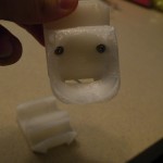
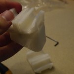
I started off by taking a long, sobering look at my x-carriage. It has been through a lot of abuse over the last three years or so. The worst indignity it had to suffer was being melted out of shape due to an incorrectly installed hot end, then bent back together with the aid of a hairdryer. As you can see the repair operation was not entirely successful.
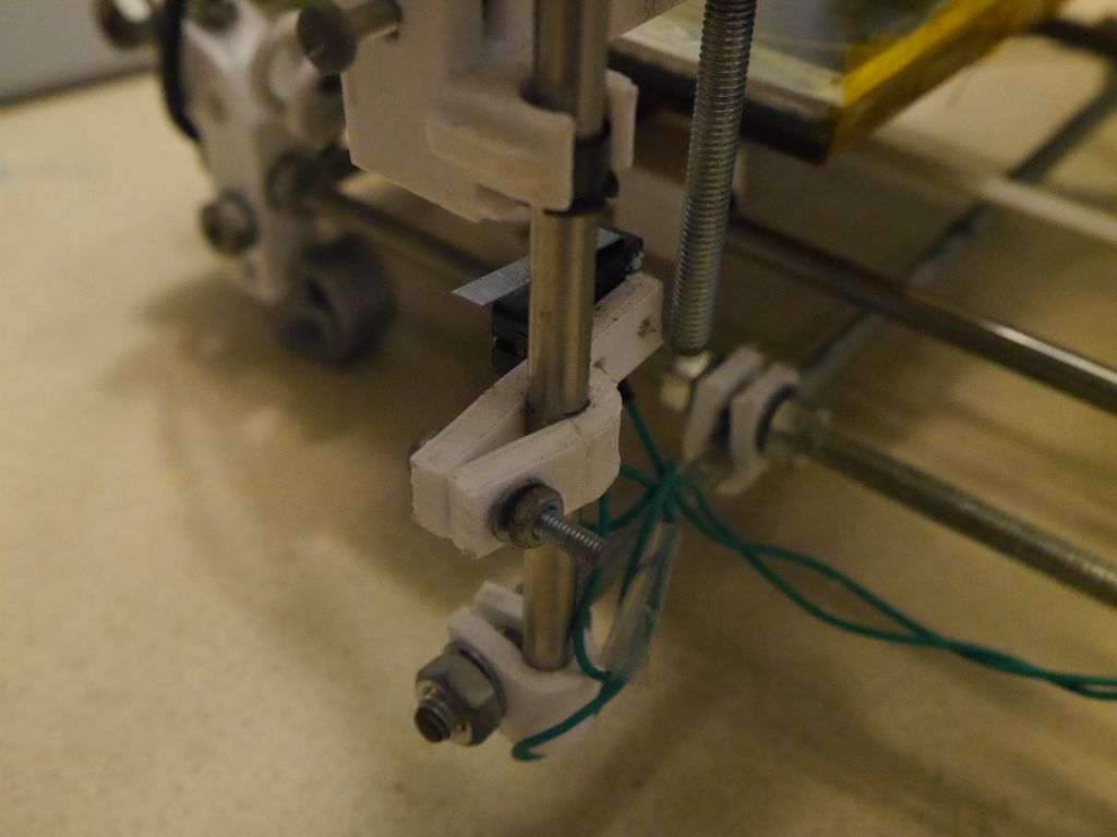
While I was at it I decided to replace my z endstop holder which has been cracked for a while. I suspect it is one of the reasons I’m always having to re-zero the z height.
Next I took apart the x carriage assembly and wondered at all the various pieces of tape and blue tack I’ve inserted over Squirty’s lifetime to “fix” problems.
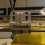
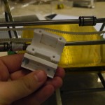
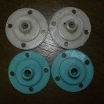
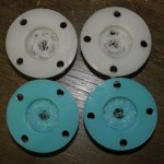
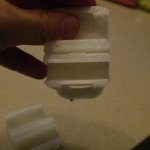
The RepRap files come with two x-carriage files “x-carriage-1off.stl” and “optional-x-carriage-1off.stl”. I printed both and as far as I can tell they are identical. They are quite different from the old version of the x-carriage I have though – check out the differences in the teeth where the belt is held in the carriage.

The teeth for the new carriage face upwards rather than downwards. At first I thought that I was meant to put two twists in the belt, but when I checked out the latest instructions I saw that they actually have an ingenious arrangement where you add in a small length of belt in the middle of the carriage which then mates with the other two ends. This is much more secure than having the belts mate with printed teeth.

The gap to put the belt into was very tight. I ended up having to shave some plastic out of the gap to make it fit, which was a pain. I am guessing this is because I have printed the outlines a bit large. I suspect that Rob had to do the same when he tried to build his printer out of my printed parts. Sorry Rob!
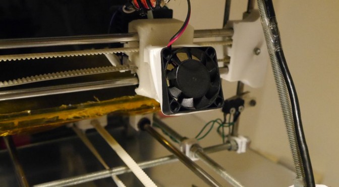
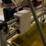
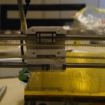
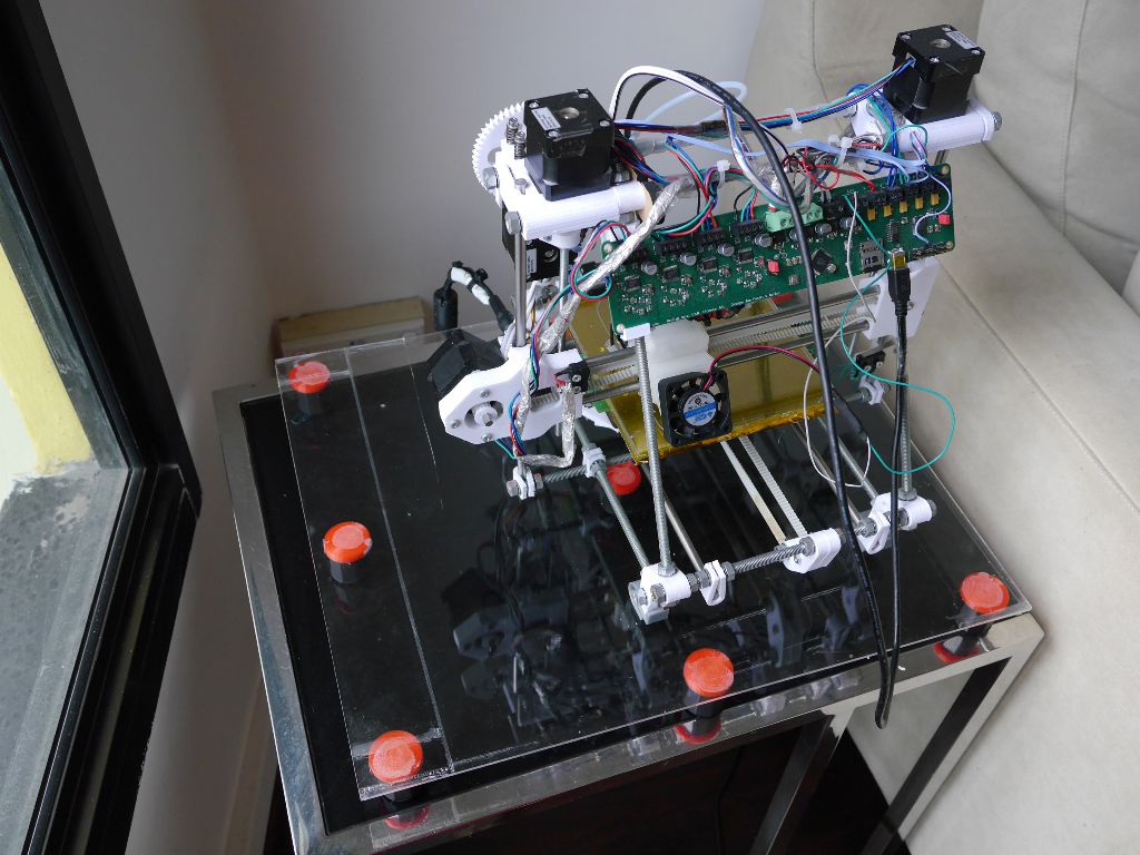
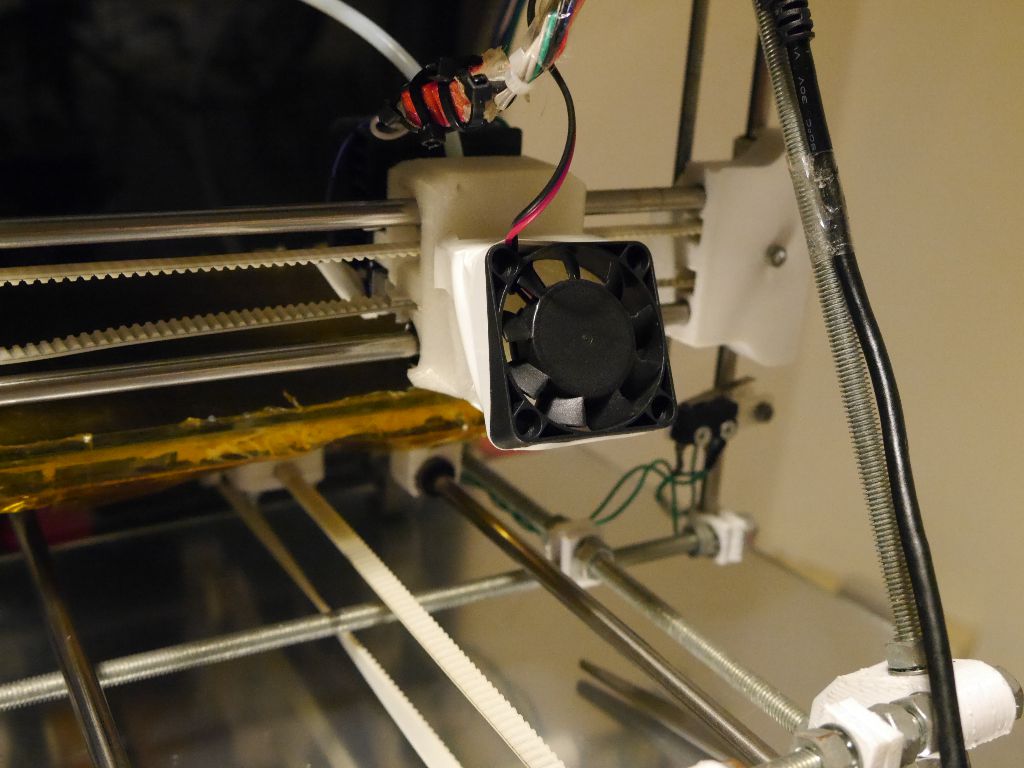
I took the x carriage out again and fitted the fan duct. I’m not sure what the “official” way of installing the fan duct is. I used a couple of short M3 bolts and drove them into the holes in the x carriage. They aren’t meant to be self threading, but it seemed to work OK.
Next step was to install the 40mm fan. I got mine off aliexpress for less than a dollar. This makes me quite scared it will burst into flames at any moment. The fan hooks over two little lugs at the top of the duct which actually keep it in place quite nicely. Before going any further I wired the fan to the Melzi board to make sure it spun OK.
After a bit of searching I found the right gcodes for turning the fan on and off. To turn off you use “M107”. To turn on you use “M106 SXXX” where XXX is some number between 0 and 255 which represents the amount of pulse width modulation.
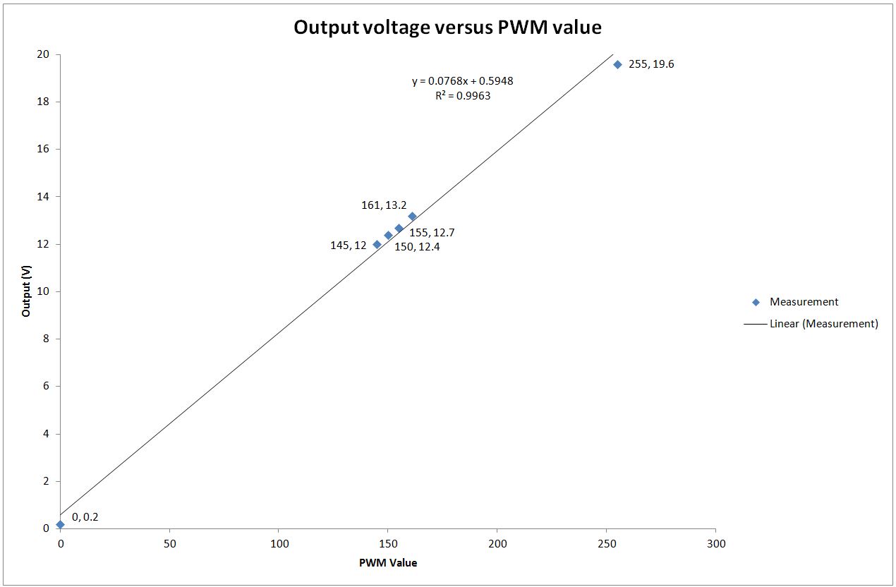
The supply for Squirty is 19V and the fan is only rated for 12V. I hadn’t quite decided how to deal with this before discovering the PWM option. The extruder fan that came with my kit is also only 12V but the instructions said to wire it right up to 19V and it has performed quite happily ever since. I had considered doing the same thing for the ducted fan, but the extreme cheapness made me worry about pushing it above its rated range. PWM gives me a safe option. You would expect that you’d need a setting of 12/19 * 255 = 160 to get 12V, but when I measured it with a multimeter (fan detached) I actually needed to reduce the setting to 145 to get to 12V.
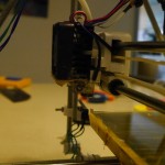
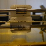
Putting a strip of paper near the output of the duct confirmed that the fan was creating a reasonable draft on the nozzle. I wrapped some electrical tape round the fan to seal the gap between it and the duct housing.
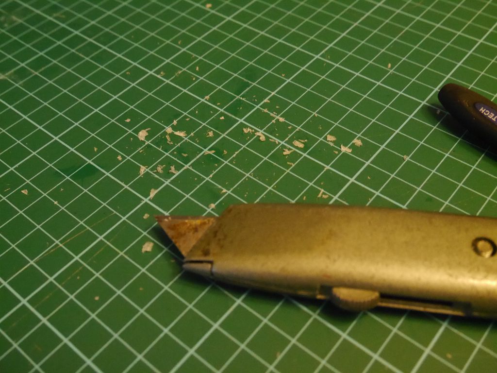
Next step was to fire it up and try it out. I turned on the printer, homed the axes… …and listened to horrible sounds as the x carriage struggled and failed to reach the x limit switch. I moved the x carriage by hand and found that it moved freely in the middle of the axis, but stuck when it got close to the edges. At first I thought that something had been bent out of shape during the destruction of the case a few weeks ago. However I eventually realised that the sticking only happened when the belt was inserted into the x carriage. Removing the belt allowed the x carriage to run freely without any issues. What was happening was that the belt was wedged in so tightly that it was pushing the x carriage apart slightly, which made the distance between the two sets of bearings too great for it to move freely at the edges of travel. I went back at the x carriage with a stanley knife and a file and eventually got it to work smoothly with the belt installed.
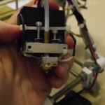
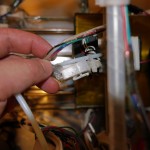
While I had the printer dismantled I also took the opportunity to repair a major bodge I made back when I installed a 0.3mm nozzle on Squirty. The original 0.5mm nozzle just wired directly into the Melzi, so removing it meant unscrewing the terminals to detach the wires. The new 0.3mm nozzle kit included a nice plug connector that allowed it to be swapped out easily. However it only included the male half of the connector, presumably because newer Huxley kits already include the female connector with the bundled 0.5mm nozzle.
I got around the problem by printing an approximation of a connector and supergluing the individual connectors into it. It has worked surprisingly well, but I have recently had a few odd problems where the extruder head pauses and then restarts when I jiggle the printer frame. I suspect this might be due to the poor quality of my makeshift plug and socket. I therefore replaced the dodgy homemade connector with a real Molex plug and socket connector (also from aliexpress).
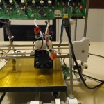
Extruder fan is now installed and has been tested on a couple of prints. First results on the hydroponics part from Thingiverse look promising, but I am going to do a proper test with some better designed test pieces to quantify how big a difference the fan actually makes.