By far the most frustrating part of 3D printing with Squirty the RepRap has always been the strange dance you have to do to get the Z distance correct. I use a strip of paper and carefully pull it back and forth underneath the nozzle while trying to bring it close enough to the bed so that the paper just starts to rub against the nozzle. At that point you can use a command to tell the printer what the offset between the Z endstop and the bed is. It is a massive pain, and this assumes that the bed is level, which it rarely is. To level the bed you need to repeat something like this at multiple points while making fiddly adjustments to the three supporting bolts.
All this faff is necessary because the printer z stop is on the frame, not the bed, so it doesn’t know what height the bed surface is at. A solution is to use a z-probe: something that can measure the distance between the extruder tip and the bed. Most new printers use an inductive or capacitive sensor to do this. Squirty, however, is a three year old RepRapPro Huxley and doesn’t have such modern frippery. There was a plan by RepRapPro to allow Huxleys to autolevel by lowering the nozzle until it pushed the bed down slightly, breaking a circuit between the heated bed electronics and the mounting screws, but it never materialised. I think this was because the electrical connection between the screw and the PCB was not very reliable.
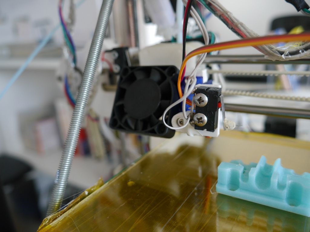
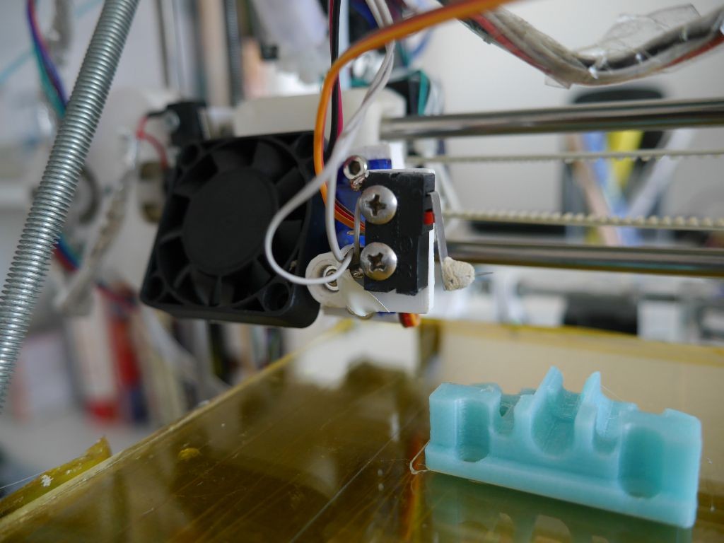
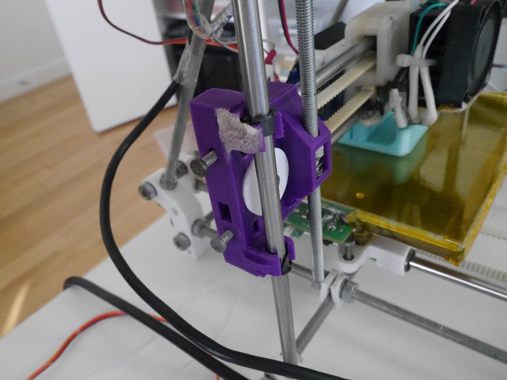
The alternative that I tried was to use a microswitch attached to the nozzle. The firmware lowers the nozzle until the bed triggers the switch, which tells it how high the bed is. The microswitch is attached to a servo motor so that it can be swiveled out of the way once this step is complete. You can see the finished version in action on my printer below.
In theory if you perform this z-probe procedure in three or more locations the firmware can then work out how tilted the bed is and then correct for any tilt when moving the nozzle, i.e. you move the nozzle up and down slightly to keep a constant distance from the bed. There is an extreme example of Luke Turner using this approach in the video below
Autoleveling is the ultimate goal, but for now I’ll be happy just getting automatic setup of the z distance.
Hardware: Servo and Probe Mount
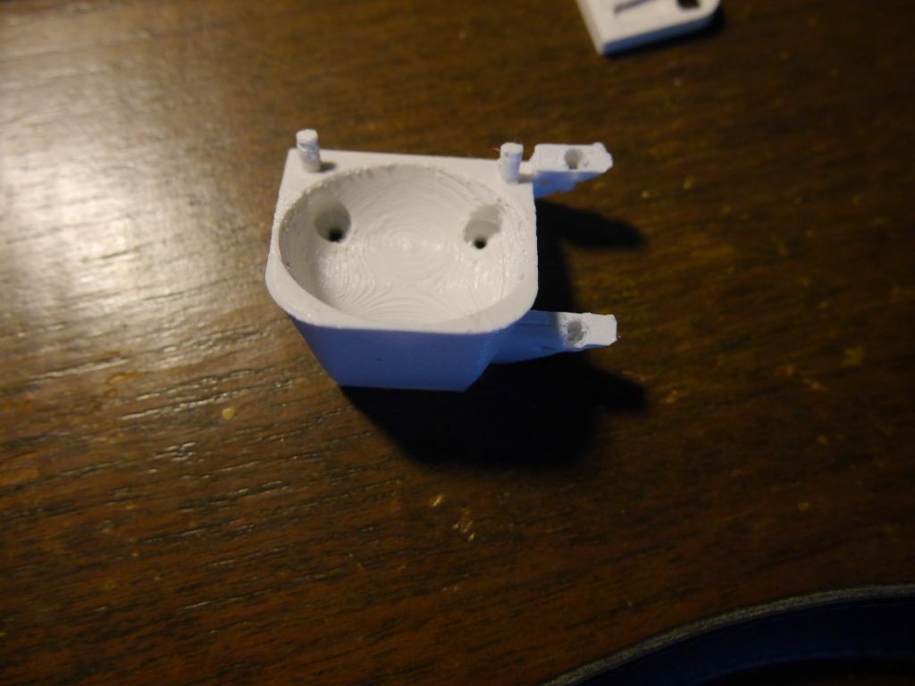
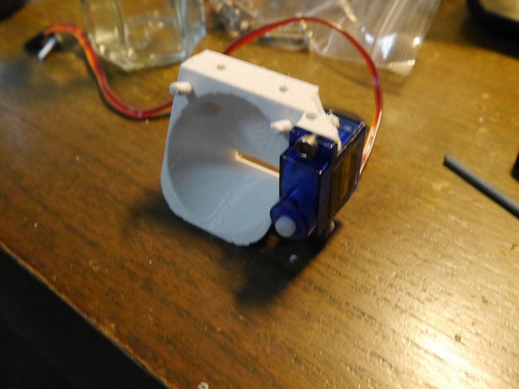
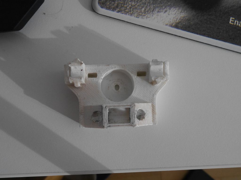
I decided that the best place to mount the z probe would be on the right hand side of the ducted fan. It can’t go on the left as it would interfere with the x homing, and anything on the other side would block the heatsink. Rather than try and glue or bolt something to the existing ducted fan mount I made a new version of the ducted fan by importing the original stl into OpenSCAD and adding two lugs to mount the servo.
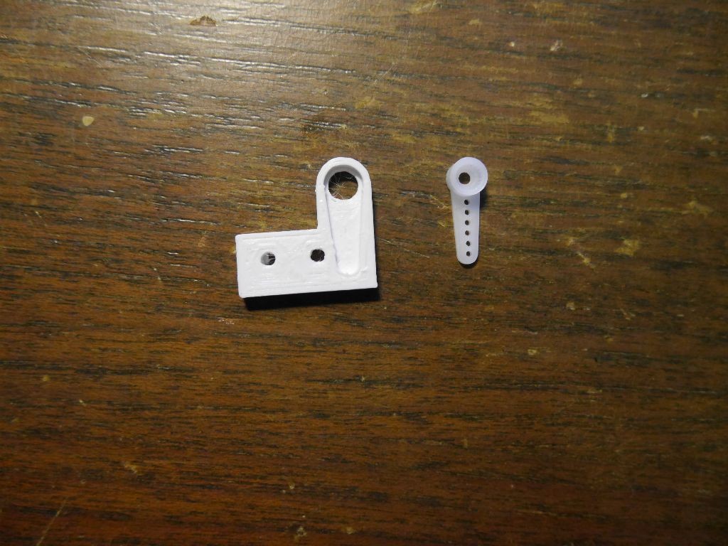
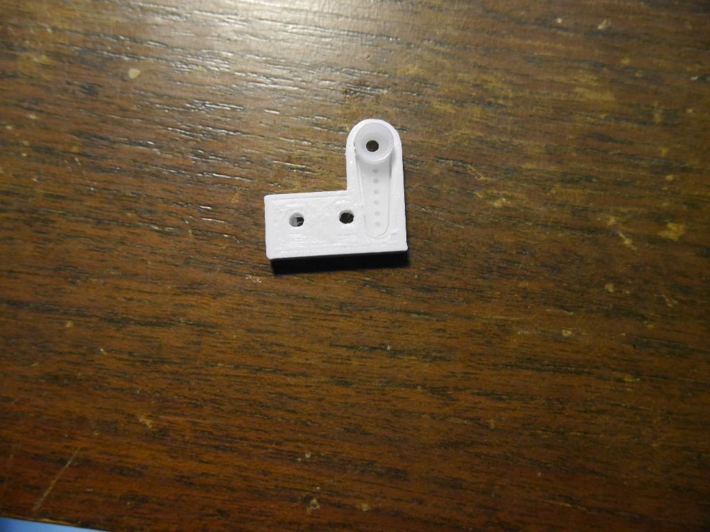
I then made a right angle bracket to attach the microswitch to. I made an inset with the same dimensions as one of the servo horns to give a secure connection.
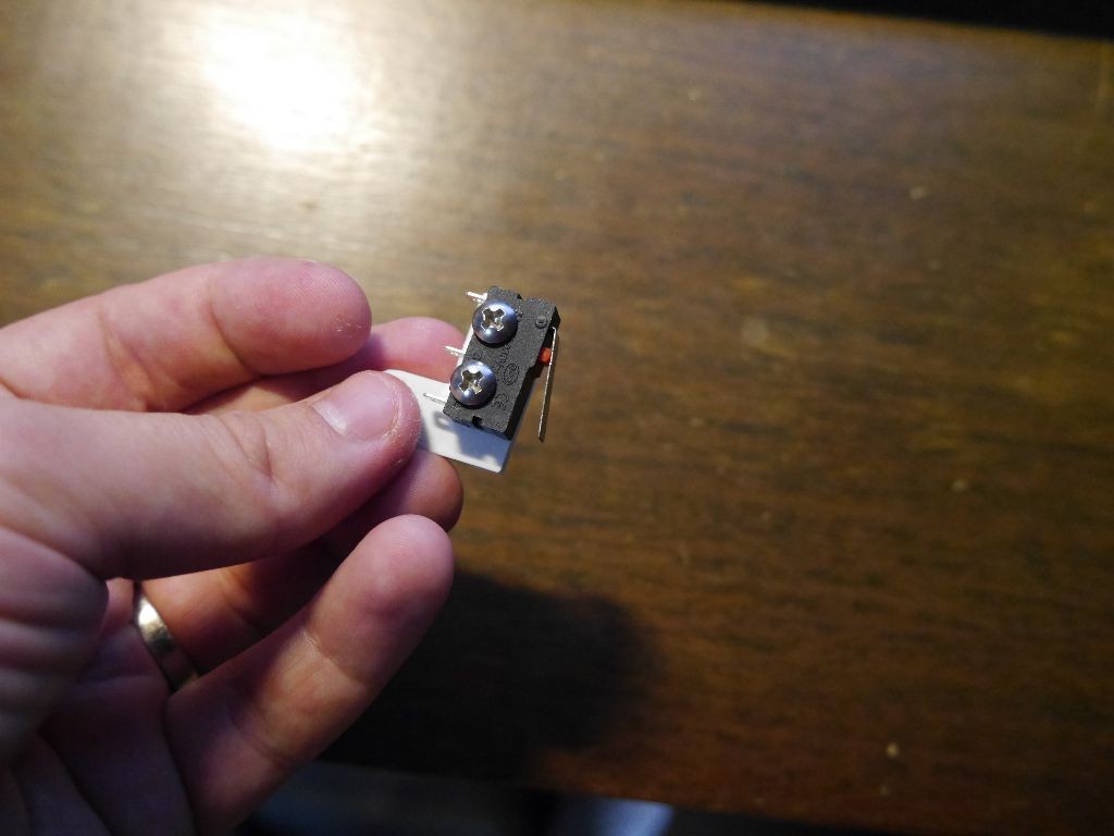
To make sure that the point that the microswitch connected with the bed was very obvious I chopped off the end of a sewing pin and glued it to the end of the microswitch with some epoxy putty. In honour of Frank Herbert/David Lynch I have named this part the “Gom Jabbar” (see 1:30 in the clip from Dune below). I have jabbed myself with it countless times since installation.
Electronics and firmware
The firmware that was originally installed on the Huxley is a RepRapPro fork of Marlin. RepRapPro added support for tricolour printing and also made it so that thermistor calculations were done on the fly rather than using a lookup table. The developers of Marlin then went on to add support for features like the z-probe and autoleveling, but these features weren’t pulled into RepRapPro’s branch. This isn’t going to change in the future – RepRapPro now sells a new version of the electronics called the Duet with a different firmware. I therefore had to decide whether to adapt the latest Marlin branch to work with a RepRapPro Huxley or to adapt the RepRapPro version of Marlin to use a z-probe. I decided the former was much easier and would also give me access to any new features that the Marlin developers add.
I forked Marlin and modified it using the RepRapPro version and this blog entry as a guide. You can see the changes I made in the “AsUsedOnSquirty” branch of the fork. As well as changing various values in the configuration.h file I also needed to add a pin for the z-probe servo and to modify the heated bed pin from 12 to 10 in pins.h. It was also necessary to make new thermistor tables for the RepRapPro thermistors.
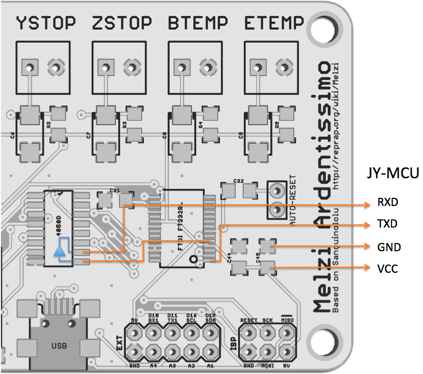
Compiling the firmware requires arduino 1.0.4 rather than the latest 1.6.5 version. You also need to download sanguino. With this software installed the board should appear as “Melzi 1284p 16 MHz”. To upload the firmware you have to set the reset jumper on the right hand side of the board.
Incidentally while looking through the RepRapPro firmware I found there were different settings for various versions of the Huxley depending on ship date, as different kits have different pulley and belt arrangements. Since I upgraded the firmware quite some time after buying my kit I suspect I have been using incorrect values for the mechanical settings for a while, in which case the dimensions of my parts would be slightly off. Rob I am sorry to say that GIB may have malformed parts!
I freaked out after uploading the firmware because there was no familiar flashing status light on the Melzi board. I wasted quite some time debugging “what went wrong” with the upload before realising that in the main Marlin version there is no code to flash the status light. In other words no flashing light means everything is working as intended. Oops.
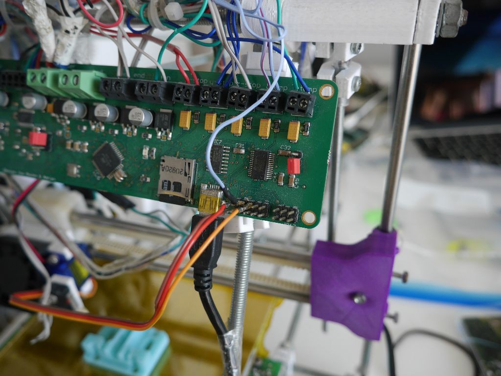
To wire in the z-probe microswitch you remove the existing z endstop and connect the z-probe microswitch to the “z-stop” terminal at the top right of the Melzi board. The servo has three wires. The red +5V wire connects to the 5V pin at the top left of the EXT area at the bottom right of the board. The black ground wire goes to the pin below it. The signal wire goes to the D11 pin (third from the left on the top row of EXT, next to the heated bed wire).
Calibration
Once the firmware is uploaded and everything is connected up you still need to define the offset between the z-probe and the nozzle. There is a good description of how to do this on the Marlin documentation page, but one thing that confused me no end is that the value for Z_PROBE_OFFSET_FROM_EXTRUDER is apparently ignored by the firmware. To set the z offset I instead needed to use the M851 command followed by M500 to save. E.g. if the probe is 12mm below the nozzle when extended then you should type M851 Z-12 followed by M500 to save. The M401 (lower probe), M402 (raise probe) and M114 (get position) commands are useful during this process.
Results
The z-probe works well and has high repeatability. There is a repeatability test built in to Marlin which you can use with the M48 instruction. The readings below were taken at a single point with the probe raising and lowering between each reading. You can see that the standard deviation of the measurements is less than 0.05mm.
Send: M48 X70 Y70 P10 E

Recv: M48 Z-Probe Repeatability test.   Version 2.00

Recv: Full support at: http://3dprintboard.com/forum.php

Recv:    z: 12.888751

Recv:    z: 12.922250

Recv:    z: 12.870751

Recv:    z: 12.855000

Recv:    z: 12.804500

Recv:    z: 12.823000

Recv:    z: 12.938250

Recv:    z: 12.859251

Recv:    z: 12.847001

Recv:    z: 12.862001

Recv: Mean: 12.867075

Recv: Standard Deviation: 0.038843
Although I’m pleased with the probe’s performance I need to make some modifications before I can use for autoleveling. I made some bad choices with the positioning of the probe that I need to correct. The x and y offsets of the probe tip versus the nozzle are 31mm and -66mm respectively. This means that the probe can’t test at the left hand 31mm or top 66mm of the print area, which is a sizeable portion of the bed. With this setup the auto level will not be as accurate as it should be. I will modify the mount so that the microswitch is much closer to the nozzle.
There are also various problems with the firmware for autoleveling in the release version of Marlin. However there is now a pre-release version that apparently has lots of bug fixes so I am going to try merging with that before I give autoleveling another go.
Squirty in the New World
This post was tricky as I did most of the work back in April and have forgotten a lot of the issues I faced. The main reason for this has been that I moved from Singapore to New York in May, and in the move Squirty suffered a lot of damage. Several of the plastic parts including the x idler bracket were broken, and I foolishly did not have a full set of printed spares. The z axes also fell off the frame which meant that I needed to reattach them and then adjust the x axis to be properly horizontal again. Hack Manhattan helped me print some replacement parts, but the breakages plus the half finished state of auto levelling was a bit overwhelming (and I did also have to look for a job) which is why I only printed my first part in the US yesterday.
Now Squirty is up and running again and I have a little bit of time before starting work I hope to make some progress on the long list of improvements I’ve been meaning to make to it.
If I pay for your flights back to Blighty, will you upgrade GIB too?
Er… yes! Shouldn’t be necessary though – I’ll upload the part designs once I’ve made the modifications then you can print them out.
almost everything is clear. but I connect display. and that one blue wire goes there?how can you tell in the firmware to activate the servo ( angle of rotation) and what else the firmware needs to be changed)))
Hi Oleg. If that pin is not free I believe you can use one of the other digital output pins (D16 or D17 in the diagram in the post). You need to change the pin number for the servo in pins.h of Marlin. You can see pins.h in the version of Marlin I am using on github here: https://github.com/jweob/Marlin-for-Huxley-MarlinFirmware-/blob/Development/Marlin/pins.h The servo pin is on line 1222. The servo angles are in configuration.h on line 761.
If you have Melzi and a RepRap you could try just using my fork of Marlin, or you could see the changes I made to the main fork here: https://github.com/jweob/Marlin-for-Huxley-MarlinFirmware-/commit/a2f80750107181f0c21f325c6731d0e59aa50623
Good luck!
PS I should clarify that in my setup the blue wire going in to pin D10 is for switching on the heater bed. The orange wire going in to D11 is the servo.
Good day. EXT connector on just wearing the contact group screen and I can’t know used contacts D11, D16, D17. if I plug the servo on D11, then this will impact on the work screen or not?
Sorry I don’t have any experience with screens.
5V and GND can be rented from the ISP connector?
I took 5v and gnd from the left side of the ext connector
I apologize for my English. my native language is Russian and I bad speak English )))
disaster struck . I did everything according to the instructions . firmware came for the first time , and then began to reign , and all … I can not fill http://www.imageup.ru/img121/2371180/bezymyannyjj.jpg.html
gives an error
Was this while you were trying to upload the firmware? Did you put the jumper on the reset pins on the right side of the Melzi board? You need to have that jumper set to upload firmware. See the picture here: http://reprap.org/wiki/RepRapPro_Huxley_maintenance
ust I think can board died . Although I do not understand why . I beg once normally and edit firmware started and extinguished . very sorry