In this post I’ll describe a safety system I’ve put together for Squirty the RepRap that should prevent the type of catastrophic thermal runaway that I experienced a few weeks ago. The system could work for any printer with a little modification (but obviously use at your own risk!).
Goals and performance
There is already thermal runaway protection built in to the Marlin firmware that I am running. However, this did did not prevent my meltdown because in my case the whole board became unresponsive, so it was unable to monitor the thermistor and turn off the heater. To protect against this scenario, I decided that I needed an additional safety system that was completely independent of the existing control electronics. The system controls the power supply to the printer and cuts the power if one of the following scenarios occurs:
- A secondary thermistor in the hotend reads an excessive temperature. Since I do my printing at 200C, I set the cutoff temperature to 250C
- The secondary thermistor goes open circuit or short circuit
- The hotend is powered for more than a minute at a time. This is less time than is needed to get to 200C from a cold start. This is designed to protect against the thermistor falling out of the hotend.
- The heated bed is powered for more than a ten minutes at a time. This is less time than is needed to get to 70C from a cold start.
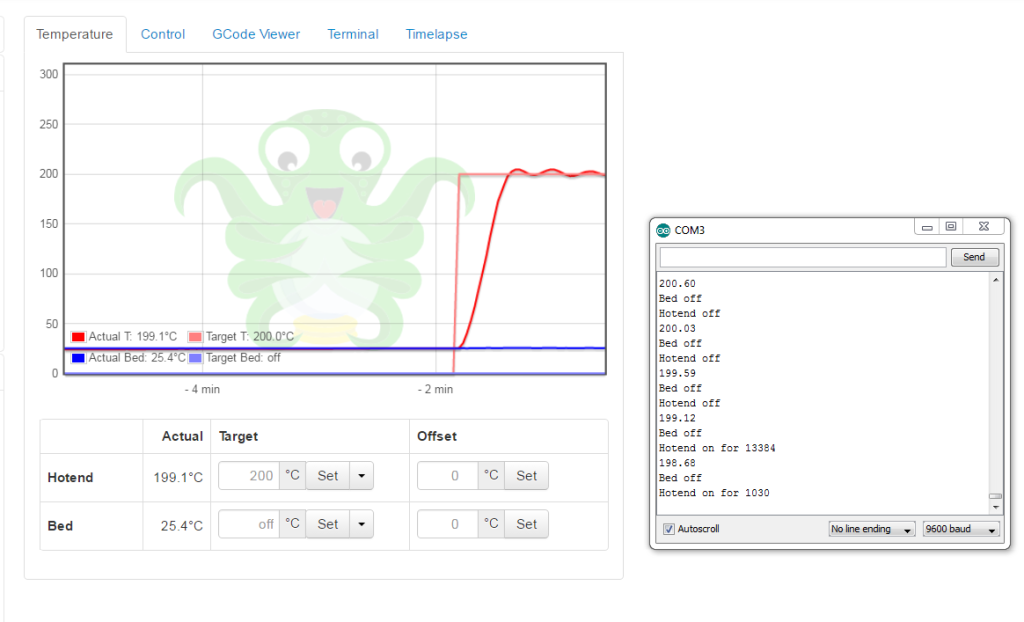
Here’s a video of the safety electronics cutting off power when the temperature gets too high.
The safety electronics outputs readings over serial to help with testing. It reads a temperature that is within 1-2 degrees of the temperature on the primary thermistor.
System description
The system is made up of:
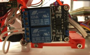
- A relay which has the Huxley’s 19V power supply running through it. I set it up so that it is normally off, so that if there is any power failure to the control circuitry the relay will kill the printer power. The relay has a driver circuit built into it so it can be switched on and off with a 5V logic signal
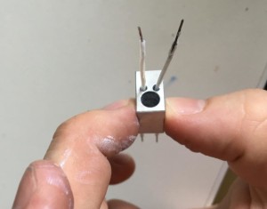
- A secondary thermistor which is placed in the hotend. It is the same 100K axial model as the primary thermistor. I like that it is axial, as it makes it less likely to fall out of the hotend
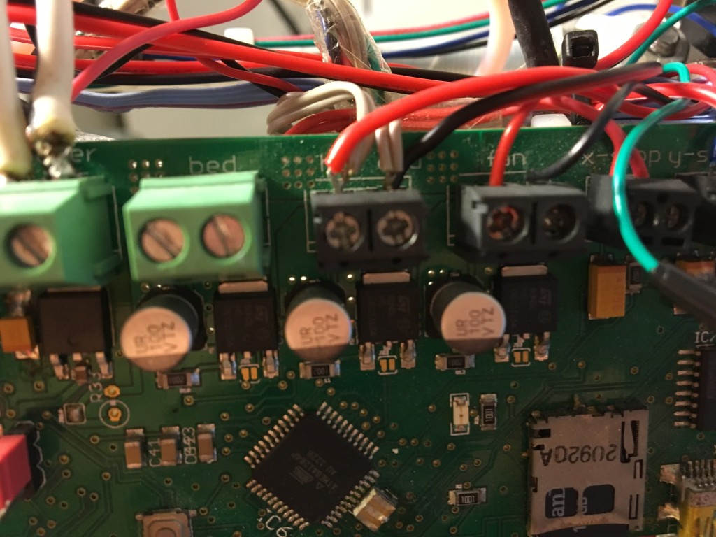
- Connections to the positive and negative terminals of the hotend heater cartridge. When the hotend is off both of these are at 19V. When the hotend is on, the positive terminal is at 19V but the negative is driven to ground. When there is no power to the printer both terminals are obviously at 0V. I needed connections to both terminals so I could discriminate between the hotend being on and the printer’s power being off.
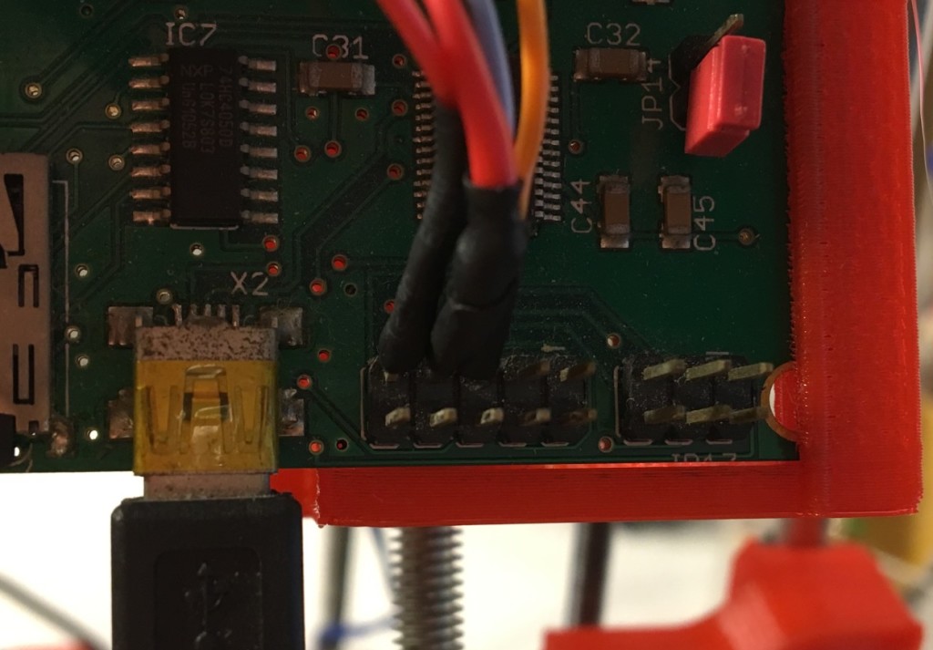
- A connection to the heated bed signal wire. The power for the bed does not go through the Melzi, instead there is a little circuit on the heated bed PCB that can switched on by a HIGH signal from the Melzi. By splicing into this connection I can tell when the heated bed is on (as long as the circuit on the PCB is working correctly)
- A connection to the main power supply’s ground terminal as a reference for the heated bed signal and hotend connections
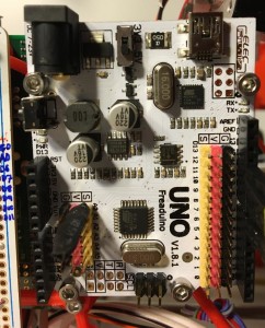
- An Arduino Uno clone (Freaduino Uno) to perform the safety logic
- An Adafruit 1/2 size Permaproto breadboard with various circuits to prepare signals for the Uno
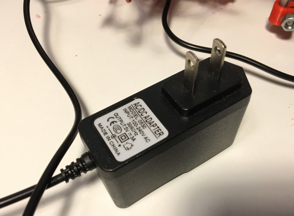
- A 5V 3A power supply to power the safety circuits and also to power the Raspberry Pi I use as a host
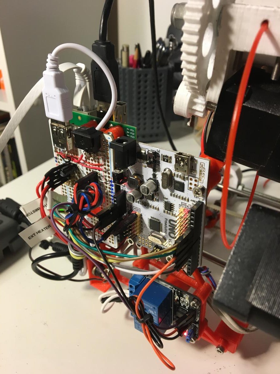
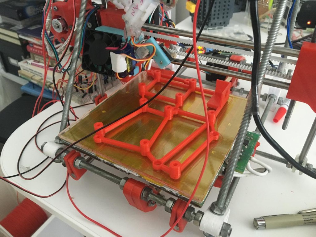
- A fancy 3D printed mounting system to keep everything in place
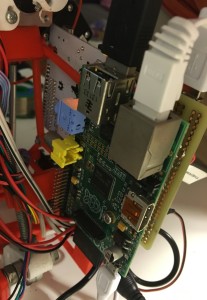
- A Raspberry Pi, which isn’t involved in the safety process but which I use to run Octoprint and which also fits on to the mount
The circuit diagram is below. The thermistor circuit is from the RepRap wiki. The potential dividers on the hotend connections are to reduce the 19V signal from the hotend to about 3.3V, which is read as as digital HIGH signal by the Freaduino. The firmware I wrote to load on the Freaduino is on Github here.
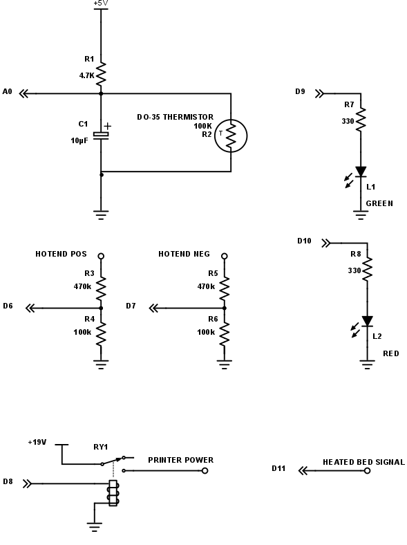
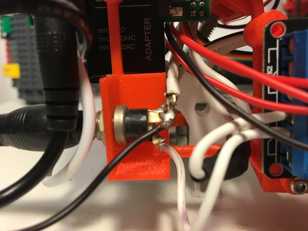
As well as the components shown in the diagram above there is a switch I put in to control power to the Freaduino. Since the Freaduino will switch the printer on via the relay this makes a nice power switch for the printer as a whole. For the last three years or so I have been resetting the printer by yanking the power plug in and out, so I switch makes a nice change. The diagram also doesn’t show a USB socket that I wired into the 5V power to supply the Raspberry Pi.
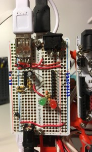
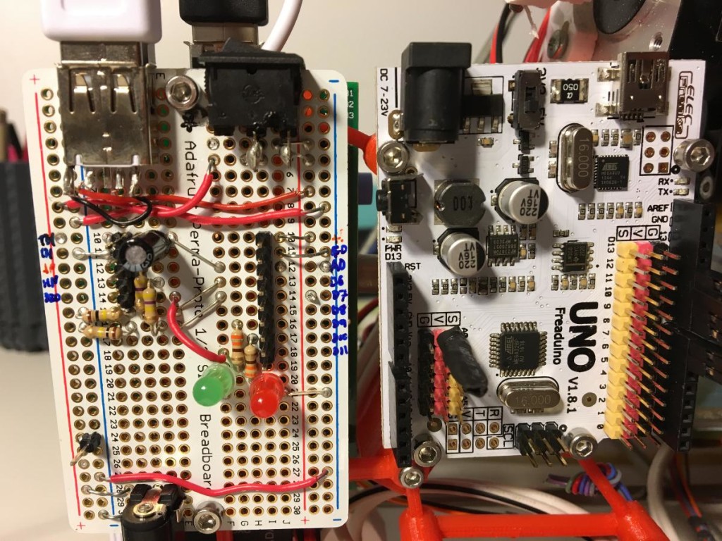
You can see how I laid out the components on the breadboard in the photo below. Originally I had the 4.7K resistor on the breadboard. However, in this arrangement if the wire between the breadboard and the Freaduino analog pin came loose, then the analog pin would be floating and could give any reading. In practice it gave a reading that corresponded to an apparently safe 170C. To avoid this potential failure mode I soldered the 4.7K resistor directly to the Freaduino between the 5V and the A0 pins.
I designed the mounts for the electronics in Onshape. The assembly is public and you can view it here. The files for the assembly are also in the Github repo and on Thingiverse.
Instructions
Here’s an attempt at instructions for setting up something similar. I’d suggest starting with long wires and everything on a solderless breadboard before starting to solder. Be careful not to accidentally attach 19V to any of the Freaduino pins (like I did, fortunately just frying one pin).
- Print out the mount, four mounting clips and two Raspberry Pi studs
- Drill a hole for the secondary thermistor in the aluminium hotend. I’d recommend using a drill press for this. I did it with a hand drill and a vice and couldn’t keep the hole very straight. Heatshrink the thermistor, apply thermal grease and insert it into the hole
- Solder up the breadboard. Solder the 4.7K to the Freaduino between A0 and 5V
- Remove the existing power socket holder. Unsolder the positive wire from the socket and solder a new short wire to it instead so that you can run the power through the relay.
- Solder a short wire to the ground part of the power socket
- Connect the mounting system to the back left portion of the frame (like this). The mounting clips have spaces for captured M3 nuts. There are also hex shaped recesses for nuts in the back of the main mount piece.
- Connect the various circuit boards to the mounting system. The Raspberry Pi goes on first and is attached to the reverse side of the mount. Use the printed mounting studs to space it away from the mount body. The holes in the Raspberry Pi are meant to take M2.5 bolts, but they can take M3 with some encouragement
- Load the firmware, wire everything up and switch on
- After switching on the green LED should light and the printer should be active. Try setting the printer temperature to 260C and make sure that the safety circuit throws the relay to switch off the printer and activates the red LED. There is a handy reset button on the Freaduino to start it up again.
- Test the other safety cutoffs. I tested the open/short circuit protection on the thermistor by just pulling or shorting connectors. To test the heated bed cutoff I set the bed temperature to 100C, which is higher than it can reach, so the bed heater just stays on continuously. The printer power was cut after 10 mins as planned. I didn’t fancy leaving the hotend on for 60s to test the hotend cutoff, but it works fine when I temporarily changed the parameter to 5 seconds instead.
I’d be really interested if anyone decides to try and make this or has any suggestions to improve it!
Design Deadends
I’ve been meaning to do this for a very long time. Two missteps helped slow down the process.
Initially I wanted to make the safety system analogue to keep it as simple and predictable as possible. However designing the circuits was beyond my level of skill, so I ended up using the Arduino Uno clone instead to perform the safety logic. This has the advantage of being easier to extend and modify than an analogue system.
I also wanted to avoid using a separate power supply for the safety electronics. My plan was to use a switching power supply to get 5V from the 19V printer supply. I soldered one up, accidentally destroyed it, then bought a cheap one off amazon instead. However I was worried about drawing more current than the 19V power supply could deal with. When I tested with an ammeter I found that the printer could draw more than the 19V power supply’s rated 6.3A if all the heaters and motors were on at once, so I decided it would be better to use a separate supply.
Next I would like to make it so that the Pi can switch off the printer once a print is done so the hotend fan isn’t left running needlessly.
will you share arduino sketch with temp calculations?
Hi Pawel, thanks for the comment. The arduino sketch is in the github repo https://github.com/jweob/RepRap-Safety . You can create a temperature lookup table for your thermistor using this script https://github.com/reprap/firmware/blob/master/createTemperatureLookup.py (please check carefully, I’m afraid I can’t remember the exact method I followed to create the lookup table)
great, thank you very much