After the creation and destruction of the case for Squirty I’ve started designing a replacement. This gives me a chance to make some improvements to the original design and is also an opportunity for me to learn to use Github, which has always been a source of wonder and mystery for me.
When I first designed the case I started out in Sketchup because I wasn’t comfortable doing assemblies in OpenSCAD. Since then I’ve read the compilation of Nophead’s early Hydraraptor blog posts put together by Gary Hodgson. In the blog Nophead describes the design process for the Mendel90 printer. His approach was to design the assembly as well as the individual parts in OpenSCAD. He even created a python script that would allow the printer to be produced in an arbitrary size with an updated BOM. If it’s good enough for Nophead then it’s good enough for me, so this time I am going to design the revised case in OpenSCAD.
Nophead also uses a github repository for the version control on Mendel90. I read an article in a recent MagPi introducing how git works and decided I would try using it for the case design.
I’ve got a few things I want to improve or fix in the design.
- The perspex for the first case took a lot of sweat to cut out because I didn’t design it in a way to make things easy to fabricate. I want to save myself some effort this time by sizing it so its easy to cut out of standard 3mm perspex sheet
- I never decided one way or the other whether the Raspberry Pi, 5V power supply etc. would be mounted on the case or on the printer. I need to make my mind up and design the mount so that the Pi etc. is not just dangling off the printer by its cables
- Regardless of how I mount it the hole for the cables was always very messy. Need a nice way for the cabling etc. to go into the case
- There was no defined place for the printer to sit in the case, so it would slide around a bit and sometimes worked its way to the case wall. Once it did that it made a lot of noise. I need to design next version with slots or ridges in the base so it stays put
- The entry point for the filament was just a hole in the case wall. This was a pain because you couldn’t lift the printer out of the case without breaking the filament. Also, once a print was finished and the filament sat there for a while it tended to break on its own. I think it was something to do with filament being constrained at the hole – I think I need to make it into a vertical slot instead and find some way of sealing it against sound
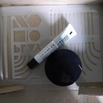
- Even though the original case design gave very good access to the printer it would be nice to be able to see it more clearly while it is running. I found some mirrored perspex at the art shop that I’m thinking of using for the base so that I can also see what’s happening on the underside while it’s printing
- I designed the base as a single sheet of perspex which was nowhere near stiff enough for carrying. Also, although the base survived more or less intact there are some cracks that I need to cover up. I’m going to use a sheet of plywood on top of the base to strengthen it, it will be covered by the mirrored perspex for aesthetics
- Probably most importantly I didn’t think carefully about how to make everything fit together neatly. I had a single upright wall that was supposed to be held at 90 degrees by a buttress and match neatly with no gaps against the lid. Even though my cutting was quite accurate there is a lot of flex and wiggle in how you join up the perspex, and even a slight misalignment gives you gaps. My Dad was visiting at the time and solved the problem by filing the case lid to fit, but I would like to avoid that this time by building it in a way that it is easy to keep the thing orthogonal
There’s also some idle thoughts I’ve had about nice things I could add on:
- I’d like to make the printer safer by including an automatic cutoff if there is any smoke detected or if any backup thermistors show a higher than normal temperature. I’ll need mounts for the smoke detector and control circuitry.
- I’ve got another Raspberry Pi camera and a long ribbon cable for it, would be awesome if I could mount it on the X carriage and link it back to the Pi so could have close-up travel-sickness-inducing printing videos
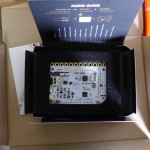
- Most crazy of all some very kind friends got me a Bare Conductive Touch Board from Kickstarter. It would be amazing if I could use the conductive ink to create a touch panel with the pronterface controls on it that communicates with the Pi for controlling the printer (current set up of iPad over VNC works OK, but the VNC can be slow)
So – a lot of things I want to do! I didn’t realise quite how many until I wrote them down.
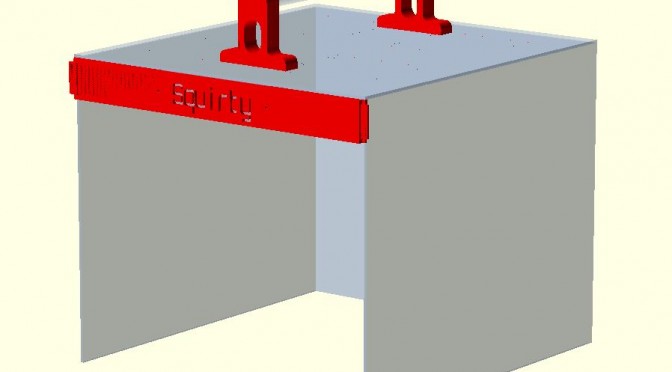
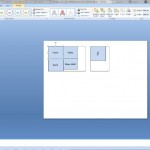
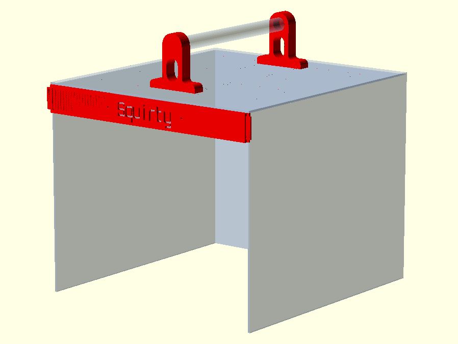
First step I’ve done is redesigning the lid to better fit the Perspex sheeting I have access to, which even in the second decade of the 21st century is measured in Imperial units (3 feet by 2 feet). It’s still 3mm thick though, what’s up with that? Embarrassingly as a management consultant my first instinct is always to do stuff in powerpoint, so I used scaled shapes on some slides to work out that if I reduced the height of the case slightly I could neatly fit the side walls into two halves of the perspex and save a lot of cutting.
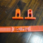
Putting stuff together in OpenSCAD was straightforward and satisfying. I’ve done the lid and attached the 3D printed parts for the assembly. Only issue I came up with is with trying to make the perspex transparent. There is a transparency feature in OpenSCAD but it doesn’t render all objects behind a transparent sheet reliably.
OpenSCAD files are all uploaded to my very first Git repository available here. Next step will be to design the new base, but I think I might finish off some pre-case-destruction work I was doing on an extruder fan first.
Good luck with the redesign of the case, there’s always features to be added, eh? Beware the pit falls of designing at the same time as building something…
One note of caution: beware about adding extra mass to the x-carriage. The position of that part during the printing process is obviously critical and extra mass might require you to modify the PID controller loop of the Huxley firmware, in the worst case, of course.
Thanks Rob, good advice. I’m going to keep hands off the case until design is complete. Noted on the x-carriage, more mass is bad. I’ve got ducted fan installed now which looks big but is pretty light, first print with it turned out OK.
Is there a PID loop on x carriage position? Thought it was open loop, or is there clever feedback happening on the stepper driver?
Oooh, how’s the ducted fan going? Have you tried a reprint of the test piece of death?
There is capacity to modify PID parameters, but I don’t think it’s for the faint hearted: http://reprap.org/wiki/Marlin#EEPROM
Good idea! I have been looking for a suitable thing to see what difference the fan makes – will try your horrific test piece.
I have printed one item with ducted fan, it was an adapter to turn a drinks bottle into a hydroponic garden (for veggies before you get any ideas). It has some quite severe bridging, but people on thingiverse said they were able to print without supports. Previously when I tried to print without fan I got holes where the bridging fell through. With the fan it was able to bridge without any holes but the first layer is very dangly. Will upload photos at some point.